I am now a big fan of remote volume control Built mine with no volumn and use a pre or my phone/pad mostly tidal thru blue os app. Very good sound and rock solid to most abuse you can throw at it. Had an issue with negative feedback so I left it out
I'd suggest you leave the 300 ohm resistors in place for now. Once the amp is up and running calculate the dissipated power as per the instructions in Part 5, Attachment 2. If it's over the 12 watts or so then change out the resistors.
Don't forget to check the DC volt in the amp to make sure the power supply caps have discharged before changing out the resistors.
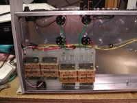
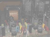
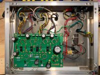
BTW, I noticed in a couple of your pictures there are some large diameter flat washers between the heads of the screws and the board. Make sure the washers are not contacting any board traces. As well, I would advise elongating the chassis hole(s) where needed so the board is supported in all five places. This will prevent damage to the board when inserting tubes.
S.
Don't forget to check the DC volt in the amp to make sure the power supply caps have discharged before changing out the resistors.
BTW, I noticed in a couple of your pictures there are some large diameter flat washers between the heads of the screws and the board. Make sure the washers are not contacting any board traces. As well, I would advise elongating the chassis hole(s) where needed so the board is supported in all five places. This will prevent damage to the board when inserting tubes.
S.
Hi, I have a Simple PP pcb and was thinking I'd like to do a push-pull EL86 triode version, using a pair of Russian 6P43P-E per channel.
I have a Triad toroid 220VCT power transformer for the plate supply, and a good 6.3VCT transformer for the heaters....
Hi Rongon,
I have built an PL84 version, which is equivalent to EL86. I documented it here, but I can see from the saga that I must have learnt some stuff since I started that thread ;-)
SPP EL86/PL84/6CW5
I noted the problem you mentioned. Once I had got the right voltages to operate the output tubes without issues, I did not really have sufficient B+ for the driver and PI, at least not to be in the same ballpark as the circuit had been designed for.
My solution was to adapt my power supply so that part of it was pseudo-choke input, to keep the voltage down for the output tubes, and part was normal CRC with a high value C at the input, to get as close to the max voltage of the transformer for the driver and PI. The board is quite easy to adapt for two B+ supplies.
My transformer is just 200 VCT. The snag was keeping the screen grid under control, and I used a 1K screen grid resistor. Maybe a 500R would work as well, but I did have red plating with the standard resistor.
I had some difficulty finding the optimum R for the negative feedback. In the end I fitted a potentiometer, and I think I have 47K on the 8ohm secondary tap. I could probably go lower, but the suggested value caused a scratchy volume control, and very distorted sound with LF oscillation. I have toroids, if that affects NFB. I have not added the capacitor yet to clean up the output square wave (saving that for when I get my oscilloscope).
I am considering adding a potentiomer for the feedback control, and a switch for different output types (P/UL/T), but in the meantime I have been enjoying music through a pair of cheap book shelf speakers I liberated from a builder's skip.
EDIT: Just saw that your version will be triode strapped, so you should have a bit more leeway on the B+. But I think 2 B+'s could still be applicable.
Last edited:
Unfortunately I installed the 300 ohm resistors, damn I’m not sure why I did that. It’s a pain to take up the board and resolder them on the opposite side but I might be able to do it through the tube holes. I do have 360 ohm resistors, so I’m not sure why I decided to use the 300 ohm resistors but I remember thinking about it
I'd suggest you leave the 300 ohm resistors in place for now. Once the amp is up and running calculate the dissipated power as per the instructions in Part 5, Attachment 2. If it's over the 12 watts or so then change out the resistors.
S.
iorrus, +1 to Steve's suggestion to leave the 300ohm.
Also, in my experience, I had the 270ohm resistors and tried JJ's and they worked fine, the dissipation was within the spec so I'm fairly sure you'll be OK
I built a similar Tubelab SPP with the Hammond 1650FA and the sound was awesome!!!
https://www.diyaudio.com/forums/tubelab/157491-pictures-tubelab-amp-56.html#post6436039
itsikhefez,
What value capacitor did you use to bypass the 5K1 feedback resistor?
Thanks, Steve
What value capacitor did you use to bypass the 5K1 feedback resistor?
Thanks, Steve
I'm not sure if you remember but I had that issue with oscillation in UL with the cap above ~300-400pF.
I was incrementally increasing the value so that the 10khz square wave looked nicer.
I think I ultimately landed on 270pF and about 2nF across the screen in the primary wiring (which took care of the instability)
I don't have that amp anymore but enjoyed the SPP enough to build another with Hashimoto transformers... really curious to see if it behaves nicer than the Hammond
The value of the capacitor is highly dependent on the OPT.
I bought 200 "guitar amp" grade OPT's real cheap about 30 years ago to build guitar amps. These have no interleaving at all, and are not very consistent from unit to unit. I have needed values from 500 pF to 1000 pF in the SPP to get the square waves right. Swapping the OPT's requires swapping the caps, so the OPT is the main factor in that cap value.
Most "experts" say to drive the amp with a 10 KHz square wave and tweak the cap value for the best square wave into a dummy load. I find the a lower frequency (around 5 KHz) correlates better with sound, especially with $16 OPT's and "bright" Yamaha NS-10 Studio speakers. Perfect square waves need response that is nearly 10 times the frequency of the square waves. My cheap OPT's might get to 25 KHz if driven by a very low impedance source. A 6CW5 or EL84 in pentode mode is not ideal for them. They work pretty good with 300B's, but who uses $16 OPT's with 300B's?
Note that this was one of the first tube HiFi amps that I ever built. It was made at a time when I got the 300B's for $25 each! It was an experiment to explore a few ideas. It is a push pull 300B amp with no feedback at all. It was built from 100% "junkbox" parts. Photo flash caps in the power supply, $16 OPT's, 10 for a penny resistors.....It defied logic, and upgrades. For some unknown reason the amp sounded great. For another unknown reason, any attempt to upgrade it, say swap out the cheap OPT's for some vintage UTC's or modern Hammonds (Edcor did not sell to end users then) resulted in worse sound. Ditto fancy parts.
This was my favorite amp for about 5 years until it blew a fuse one day during a thunderstorm. Not having a proper fuse resulted in my doing something stupid, which resulted in electrolytic goo all over the place.
This amp was one of the few old amps that I kept when I had to relocate everything 1200 miles. It is still dead, but mostly intact. I stole its power supply choke for the 845 SE amp that replaced it in my listening room over 20 years ago, also a junkbox build.
I had planned to rebuild it one day, and maybe I will......someday.
Attachments
Thanks itsikhefez,
Was the 2nF from the screen grids to ground?
George:
I hope you didn't take offence at my build series on Wall of Sound.ca. The plan was to try and make it as straight forward as possible for the next generation of tube amp builders to get a great amp. I have access to a tool and die shop but I purposely wrote the WOS.ca series using only the hand tools that the majority of builders will have available.
To my ears it's one darn nice sounding amp and the first one I build (using vintage reclaimed Heathkit trannies) inhabits my workshop. It's fed by a Raspberry Pi-based server/streamer, plays into a small pair of Triangle speakers and has provided many of hours of enjoyment. The second one built, using new Hammond "iron", sounded even better!
I know you didn't care for me drilling small holes in the board centered on the tube sockets. The purpose was to use a real part to layout the top panel. I worked for many years as a process engineer and technical writer and having a real part makes it easier to visualize and hopefully reduce errors.
Al the best,
Steve
No offence taken. I read the article a while ago when someone emailed me about drilling the holes. I found it correct and helpful.
I tend toward leaving the board, or any part, alone when I don't need to mess with it, since it's an opportunity for error. I have however hacked up several in the name of science, but I have lots of them.
It should be noted that drilling out a component hole to accommodate a fat component lead will destroy the through hole plating, possibly leading to a dead amp. This happens occasionally. The first time it happened a customer drilled out the holes in his SSE board for some monster sized coupling caps. Nobody here could diagnose it remotely, so the builder sent me the board and I fixed it.
I use a paper template that is a duplicate of the silkscreen layer on the PC board with it's outline. It can be taped to the chassis and punched or drilled through, then removed.
Some printers are not exactly 1:1 so the paper template should be verified before using.
Attachments
Last edited:
Thanks itsikhefez,
Was the 2nF from the screen grids to ground?
Looking at this picture, it looks like it was across one primary and screen.
It also seems to be a silver mica there so I may have ultimately used a value smaller than 2nF...
This was to solve some instability when approach max. output power.
trobbins tried to diagnose the problem, and said: "It may well be that the cap reduces the gain sufficiently at higher frequencies such that the stability margins improve once feedback is connected."
Attachments
Hi Itsik,
You are the only person that I know of that built both this Tubelabs SPP and the Baby Huey with EL84 outputs. Would you be willing to describe what you heard?
You are the only person that I know of that built both this Tubelabs SPP and the Baby Huey with EL84 outputs. Would you be willing to describe what you heard?
Francois,
It would be impossible for me to compare. I was using the SPP with Hammond OPT's at a previous home, in a fairly small room that was not ideal acoustically. Nonetheless, I really enjoyed that amp with a pair of Klipsch Quartet speakers. I sold it a few months ago as I'm building an upgraded version with Hashimoto iron.
The Baby Huey that I recently finished has a small hum issue, so haven't given it a serious listen yet. Besides that, I'm in a new place now in a larger room with treatments, so would be very hard for me to try and compare the two.
Aside from sound, I will say that the SPP is way easier to build than the BH. Less parts, no need for bias transformer, no adjustments, readily available power transformers, etc.
I'm close to finishing my second SPP and I just measured the amp with Mullard 12AT7's and Sovtek EL84M tubes. THD is 0.08% at 1W and 1% at 11W, with flat frequency response.
Overall I can highly recommend it
Regarding the in-progress build, I'm trying to determine the ideal feedback capacitor.
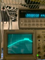
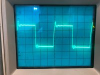
I took the feedback from the 16ohm tap and measuring a 10kHz square wave to the 8ohm taps (8ohm resistor used as load)
Attaching pictures of no cap, 120pF and 270pF.
270pF seems good but is it too rounded and better to use something slightly lower?
Unlike the Hammond 1650 from my previous SPP, no signs of oscillation or instability with the Hashimoto's.
Attachments
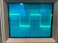

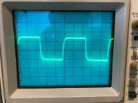
For future reference if anyone ends up using the same transformers (HW-25-8), the 390pF actually caused instability afterwards and I landed on 240pF for the compensation cap.
I have a 12” X 15” piece of aluminum I could use as top plate is this big enough? I could do 12x17 just have more scrap
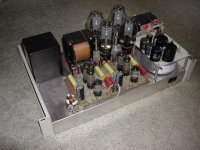
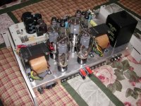
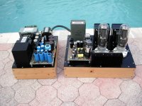
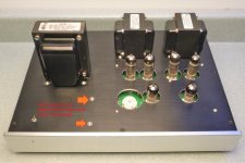
I built one in an 11" x 17" chassis. You can probably go smaller. It's best to keep the OPTs to one side and close to the back, the power trans towards the opposite side. Keep the lamination stacks of the power trans at right angles to the stacks in the OPTs to minimize interference. The use of a Hammond 156R choke in the PS reduced hum in virtually zero. The chokes laminations were arranged to be at right angles to the power trans laminations. See attacked pic.
S.
S.
Attachments
Hi all,
Let me take a second to thank George for putting together enough information and design to guide someone in the right direction.
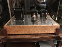
There's just one thing thats bugging me. I don't understand the tube situation. I was under the impression that the standard SPP took 6 EL84's and a rectifier. However, the pictures i've been seeing have 4 EL84's and a smaller tube in front. Can someone explain? Or is these just different variations.
I am closing in on power transformers. Im thinking of getting a custom torroidy. Does anyone advise against this or toroids in general?
What about the HV winding, it says it should be rated for at least 175 mA DC output, but what rating is recommended if you were having one built.
I bought 6 EL84m's, idk if thats gonna change or what.
Thanks in advance
Jerin
my B-side question: I have a console in mind. I would assume that you always go with the shortest possible distance between connections, but I was wondering if you could align the tubes horizontally and what the materials would look like to connect them if it didn't hurt anything? Or would it just need to be a board laid out like that?
Also, does anyone have a link explaining the differences in the modes of the output transformer?
Let me take a second to thank George for putting together enough information and design to guide someone in the right direction.
There's just one thing thats bugging me. I don't understand the tube situation. I was under the impression that the standard SPP took 6 EL84's and a rectifier. However, the pictures i've been seeing have 4 EL84's and a smaller tube in front. Can someone explain? Or is these just different variations.
I am closing in on power transformers. Im thinking of getting a custom torroidy. Does anyone advise against this or toroids in general?
What about the HV winding, it says it should be rated for at least 175 mA DC output, but what rating is recommended if you were having one built.
I bought 6 EL84m's, idk if thats gonna change or what.
Thanks in advance
Jerin
my B-side question: I have a console in mind. I would assume that you always go with the shortest possible distance between connections, but I was wondering if you could align the tubes horizontally and what the materials would look like to connect them if it didn't hurt anything? Or would it just need to be a board laid out like that?
Also, does anyone have a link explaining the differences in the modes of the output transformer?
- Home
- More Vendors...
- Tubelab
- Tubelab Simple P-P