George,
Any reason the powerdrive circuit would not pass through a positive bias voltage?
I'm thinking of putting a coupling cap and powerdrive circuit on a piece of perf that that could sit where the coupling cap normally goes, since the pcb has a pretty good space allocated for a coupling cap. I have some spare MOSFET's; thought I might give the SV572-160 a go in the next few weeks, since it looks otherwise compatible with the 12AT7.
Have you tried running the 45 or 2A3 into single ended A2? I know you said 300B goes A2, but didn't put out much more power.
I guess talk of putting MOSFET's back in, is the penultimate trainwreck of a thread that started with taking them out ...
Win W5JAG
I guess talk of putting MOSFET's back in, is the penultimate trainwreck of a thread that started with taking them out ...
What goes around, comes around. That's what experimenting is all about.
The PowerDrive works fine with a static positive voltage on the gate. I used one to feed an 833A which needed about +50 volts at idle, and swung up to about +150 volts on positive peaks. Peak grid current was in the 250 mA range......big heat sink needed on the mosfets! I doubt that you are going to find a bigger tube to wire into the TSE. In fact I used the entire TSE with a 45 to drive the PowerDrive board that fed the 833A.
Have you tried running the 45 or 2A3 into single ended A2? I know you said 300B goes A2, but didn't put out much more power.
The 45 is specced for AB2, and the TSE runs it in A2. Just how much more power I get out of it compared to what I would get if the grid never went positive, I don't know. My 45 based TSE makes a bit over 2 watts with a 5K load on 320 volts.
I stick 300B's in the same amp and I get about 5 watts, but that's running them on just over 300 volts (the wimpy power transformer doesn't like it) on about 70 mA per tube into the same 5K Electra Print OPT's. Again I never measured it without positive grid swing. For the past 10 years the amp has used some NX-483's that I pulled out of a flea market find radio. They are essentially 45's with a 5 volt filament.
I had an amp I called the 300Beast. It ran 300B's in push pull on about 360 volts into a 6.6K OPT in AB1, no PowerDrive. That amp was made out of 100% junk box parts and a set of used Russian 300B's I got at a hamfest. It made about 28 watts at clipping and about 12 watts while remaining in class A.
I really liked its dynamic sound, but it blew up in a most spectacular manner one day. I had forgotten about the 6 amp fuse that I stuck in the amp when I built it, and one of the junk box photoflash electrolytics shorted, taking out the diodes and spewing goo all over the amp. It's the only amp I saved from the "old days" before Tubelab existed. I will rebuild it some day, but it has been robbed for several key parts. The rebuild will use PowerDrive, and a new driver board that I have already made. 300B's or 307A's....I'll just have to try both.
So, I think I have the heater issue sorted out on the 801 TSE, not to say it can't stand some refinement, but I think the current issue is resolved.
Flip the diodes and caps on the TSE 801 board to get a positive bias, and voltage double a B+ line for the power tubes; try to keep it between 700 - 800 vdc, conceptually, looks fairly easy to migrate SV 572 to the TSE 801 thread. No doubt some practical problems would rear their head, but it looks like a logical extension of the SV 811 experiments. Might not even be necessary to voltage double the B+.
Remember the thread when Dyna Saur posited putting 6DZ7 on the SSE board? One of the other things I've been mulling around for that coupling cap space on the SSE pcb, was a single MOSFET split load phase inverter, that would drive a 6DZ7, putting both channels of a push pull amp on a single SSE board. I see there is now a thread up in the main forum on such a phase inverter. I don't think a tube inverter can be squeezed into that space, unless it is a sub miniature type. I'm not sure I have any.
Win W5JAG
Last edited:
Swung by the local TV / Radio supply store at noon to grab some resistors, and they were closed - as in, gone out of business closed.
My late grandfather used to take me there to buy radio parts as a kid, and since he was one of the first ( if not, the first, "radio man" here - there is some evidence of that ) he had been going there since radio started. I even had my own account.
I guess when people quit building it hurt them a little bit, when repair guys became board replacers, or it just went straight to the landfill, it probably hurt them more, and when virtually all of the local appliance manufacturing industry headed south of the border as fast as they could in the last six or seven years, the death spiral was inevitable. The United States Postal Service's bizarre policy of shipping parts from China for "free", when they gouge me an arm and a leg to send legal process to the next town over, probably didn't help either.
Wife and child are on "staycation" at our lake house, so tonight would be time at the shack bench for me, but unless I can find some load split resistors at home, and I pretty well scraped the bottom of the barrel to come up with some mostly unsatisfactory ones to get the mule going p-p, I probably won't be building a phase splitter of any type tonight.
Not at all pleased about this.
Win W5JAG
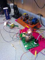
I have SV572-160 running on the modified SSE board right now.
Grounded cathode through the center tap of the filament transformer, 12 volts positive bias on the grid shows 7 ma grid current, 400 volts dc shows 80 ma plate current. A real wiring rat's nest with two power supplies and the filament transformer.
Unmodified 12AT7 front end, and it sounds quite good through a test speaker, but as expected it appears to lack the stones to drive the power tube without PowerDrive. Haven't tried to measure anything else.
This looks like it could be worth building up a power drive board to see where that goes.
I may see if I can find an 811a here, without having to remove the 30 odd screws to pull one from the Ameritron.
Win W5JAG
Found a gnarly looking RCA 811-A here, may or may not be good. My TV-7 says it is, but that doesn't mean it is.
It's working on the board now, but is behaving quite differently than the SV572-160.
It worked, sort of, at zero bias, or just slightly negative, but wouldn't pull any current. So, I put some resistance in the cathode; right now, I have 1.2K and a bypass cap on the center tap, and about 45 volts positive on the grid, this shows 5ma grid current, and about 40 mils at the plate at 400 vdc. That's probably a net zero to slightly negative bias, but it's the only way it will pull current.
It has quite a bit more gain than the 572, but audibly seems not as clean. Same unmodified 12AT7 front end.
Odd. Or interesting. Not sure which.
Win W5JAG
edit: 10K load on both tubes.
Last edited:
This 572B is dead, even the TV-7 says so. I've been saving it to build a nightlight for my four year old, as soon as I can spare a filament transformer.
Regardless, it worked on the SSE board, and sounded the same as the SV572-160, although it took the same quirky set up as the 811A to make it do anything worth listening to.
I spent a fair amount of time listening to the 811A this afternoon, and had it not been so drizzly/dreary here, I might have gone out to the warehouse of junk to grab some new 811A and 572B to see if they behave as these dregs do.
I had believed that the SV811-X and SV572-X tubes were the transmitting tubes, except for the different mu's and lack of a plate cap. I'm less sure of that now, but I think I have quite a few, enough for a decent sample, of new Svetlana 572B at the warehouse, so at some point it will be easy enough to put that to the test.
Out of this bunch, the 811A is now the one that interests me the most.
Win W5JAG
Attachments
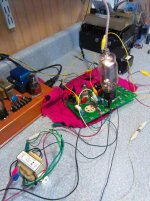
This would be a tight fit, but looks possible.
The big PT has two ( 2 ) robust 2.5 volt CT secondaries, so that eliminates the need for filament transformers, but lacks a 6.3 volt secondary, adding an additional problem. It's also 400-0-400, making a choke input mandatory. The choke would have to go under the cake pan. This would be robust and well suited for 45, 46, 47, and 2A3.
Since I would have to add a filament transformer, the little Thordarson pictured has both a 6.3 volt secondary suitable for the 12AT7, as well as a 115 volt secondary; fixed bias would be added to take advantage of that extra secondary, might as well put DC on the 12AT7 filament.
The OPT's pictured are not great, but are suitable enough for this purpose. The 10 watt open frame Edcor XSE would probably fit here. If actually built out, this would slot in somewhere between the Simple 45 on the web site, and the TSE.
The test board now has red LED's on the front end, in place of the resistor/bypass cap combination. I selected these on a trial and error basis. I took an arbitrary B+ voltage, measured the current at the cathode, then started swapping in LED's until I got a match. These nondescript red's turned out to be a good match. I changed the current set resistor in the CCS to 470 ohms.
This seems to work pretty well with a 12AT7 at anything over about 250 volts on the test board, with good front end gain. With a 45, and a Transcendar 5K OPT, I was seeing about 3% two tone IMD with the 12AT7 at one half watt, going up to about 8% at 1 watt, so a pretty good improvement over the previous iteration with the 6189.
I spent most of the afternoon listening to the NFL game through it, and it sounded quite good through the test speaker, seems stable as long as it has an input connected or shorted.
Win W5JAG
Attachments

like W5jag I've found when the voltage is below 300V and particularly as it approaches 250V the sound starts to deteriorate rapidly with the 12AT7 in place. Also like him I've found that substituting with a 12BH7 is a good fix for this.
In a design like the SSE where the CCS tries to keep the plate current at 8 to 10 ma, the voltage at the grid starts to get pretty close to zero at lower plate voltages. Try lowering the CCS current if you want to run them below 200 volts.
Tinkering with both the CR SSE, and the modified board here, 230 volts or so was about as low as I could get 12AT7 to go. 470 ohms as a current set seems to be good to about 250 ish, and 560 ohms seems to be good to about 230 ish with a good cross section of U.S. made 12AT7. 680 ohms produced unacceptable results on my boards, so it looks like the practical current floor is somewhere around 5 ma. For someone who doesn't mind adjustments, the current set resistor could be a useful place for a trim pot.
With my limited equipment, IM distortion was marginally worse with the lower current 12AT7 compared to the full current 12BH7, but the gain structure is restored. FWIW, I'm presently using the 12AT7 and 560 ohms on the CR SSE, as I didn't consider the IM significant.
One other thing of interest, I observed that one tube in particular, a NOS Ei Elite, that wouldn't work at all in a full voltage, full current, SSE, works quite well at the lower voltage, 5-6 ma current, setting. I also observed that an EH 12AT7 seemed to have a lot less gain than my other 12AT7. I only have one example of this tube, so that may or may not be typical of the type.
I'm using 25-30 year old red LED's for the 12AT7 bias on both boards. After reading up on this, I have no idea whether I went through the correct selection process. I didn't see any distortion difference between the LED and the RC combination; if anything, the LED might be slightly better. It sounds fine, so I guess I haven't botched anything. I'm wondering if a secondary artifact might be a visual indication of tube health and aging.
Win W5JAG
Attachments
Tinkering with both the CR SSE, and the modified board here, 230 volts or so was about as low as I could get 12AT7 to go. 470 ohms as a current set seems to be good to about 250 ish, and 560 ohms seems to be good to about 230 ish with a good cross section of U.S. made 12AT7. 680 ohms produced unacceptable results on my boards, so it looks like the practical current floor is somewhere around 5 ma. For someone who doesn't mind adjustments, the current set resistor could be a useful place for a trim pot.
Good info to know W5JAG.
I might check this out some time in the future, my board is bolted under the
top plate of my amp and I'm too lazy to disassemble then reassemble everything
to try this anytime soon.
Right now I'm quite okay with the lower gain using a 12BH7 or 12AU7 when running
low B+ voltages. Whatever additional distortion there may be is not apparent to
my tin ears. Apart from several multimeters I don't have any measuring equipment.
I've rigged up my low voltage SSE so that depending on the rectifier, power tube
and cathode bias resistor in circuit I can get B+ voltages from around 140V to
close to 360V. As such I am able to run tubes like 6Y6, 6W6, 6V6, 6F6 and a bunch
of other tubes. I've also run 6BG6 tubes in this amp with very good results, these
tend to red plate in my high voltage SSE.
What I'd really to learn about is any ideas for adjusting screen grid voltages. That
is if there is a feasible way of adjusting screen voltage to several different voltage
points without compromising the SSE's performance and if so, what modifications are
required ?
The screen grid of the output tubes goes to the OPT connector. The 3 pins on the connector are Plate - Screen Grid - B+. You wire the screen grid to the plate for triode, the UL tap on the OPT for UL, and to the B+ pin for pentode.
The simplest way to run pentode with a reduced screen voltage is to build a small mosfet regulator on a piece of perf board and wire it up to the OPT connector. This way no changes at all are needed to the main SSE board. The regulator needs a connection to B+ (available at the OPT connector), ground (available at several connectors, but use the aux cap connector to avoid possible hum issues) and the screen connection on the OPT connector. One board can feed both channels.
Copy the screen regulator from Pete Millett's Engineers Amp, AKA the big red board. Just about any N channel mosfet that can eat the B+ voltage with some safety margin will work.
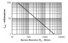
Top secret info......the 6Y6 and 6W6 will both work fine with up to 400 volts on the plate, IF you keep the screen voltage in the 110 to 140 volt range. Most of my experiments have been in push pull mode where I have squeezed 40 watts from a pair without blowing anything.
The simplest way to run pentode with a reduced screen voltage is to build a small mosfet regulator on a piece of perf board and wire it up to the OPT connector. This way no changes at all are needed to the main SSE board. The regulator needs a connection to B+ (available at the OPT connector), ground (available at several connectors, but use the aux cap connector to avoid possible hum issues) and the screen connection on the OPT connector. One board can feed both channels.
Copy the screen regulator from Pete Millett's Engineers Amp, AKA the big red board. Just about any N channel mosfet that can eat the B+ voltage with some safety margin will work.
Great. Thanks for that info George. I'll have a look at this and see if I have the brains to implement it.
It also has a nice MOSFET ripple filter. Just sayin'.
Win W5JAG
Any great benefit to adding the ripple filter ?
I have both the FRED's and tube rectifiers installed.
The mosfet ripple filter is a substitute for a choke, so, no reason to add it to your setup.
Win W5JAG
Win W5JAG
I can't say I've made an exhaustive search, but I've not been able to find any AB operating points for push pull 6G6G ( or 6AK6 ).
Trial and error for 6G6 has got me to -10 volts bias for class A, and -20 volts bias for AB.
For AB, I have pentode mode, cathode bias, 280 volts on the plates, 10K plate load, 1100 Rk and 1000 ohm screen resistors.
Pd is 4.75 watts/tube, and it starts to show crossover distortion at 3 watts into an 8 ohm load. Looking at it on the scope, it looks like the early distortion is coming from the split load section - there is some visible asymmetry there. I probably need to tweak the resistor values, but with the local radio shop closed, this is problematic. I'll have to order in parts.
Win W5JAG
The mosfet ripple filter is a substitute for a choke, so, no reason to add it to your setup.
Win W5JAG
Yes, I realized after I posted that I asked a foolish question due to not carefully reading the documentation on that amplifier.
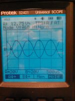
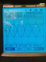
This is the output of the phase inverter, taken at the cold end of the coupling caps / grid of the power tubes, showing one half running out of gas well before the other. Phase invert looks OK, amplitude, not so much.
Results are similar with 12AT7 and 12AU7, and several examples of each type, so not likely a tube problem.
1 kHz sine wave input, 68K plate resistor on the input side, 20K on plate and cathode of the inverter, 0.1 uF coupling caps, 470K grid resistors.
I would think I need closer to 33K on the phase inverter, but I used what I could find at home on a Friday night to make it work; I don't stock a lot of 1 watt and higher resistors since I don't use them much.
It does work well up to the point this asymmetry occurs, and I don't need more than 3 watts from it; I just expected 5 or 6 out of it.
Win W5JAG
Attachments
I found another barrel to scrape.
In between the warehouse of junk, and what gets binned / shelved, there is the intermediate cabinet of sacks, one of which yielded up some baggies of resistors, mostly unsorted 1/2 watt carbon comps, but one had some nice 1, 2, and 3 watt carbon comps, including almost a dozen really nice, flameproof, 3 watt, 39K pieces.
I put two of those, measuring 38.5K, in place of the existing 20K's at the output of the split load, and that seems to have cleaned up the front end nicely.
The below pic is of the mule front end, same 1 kHz sine wave, with the mule doing about 3.25 watts into 8 ohms, which is all I can eke out of it. At this point, it just begins to show the beginning of crossover distortion, and the beginning of sine wave compression.
Am I being unrealistic in expecting more than this from it? Should I bump the coupling caps up to 0.2 or 0.3 uF from the existing 0.1 ?
These tubes only draw 150 ma filament current each, and 3 watts is adequate for my needs, so maybe I am being greedy expecting more, but if there is more to be had, I'd like to get it as a matter of principle. I still think the plate load is a little low at 10K, but it's all I have right now.
One other thing, in addition to not finding any operating points for push pull operation, the RCA data sheet for 6G6 also omits a grid resistor spec. My Tung Sol books show a max of 0.5M for 6AK6, so I've been using 470K. My index finger told me one of the 6G6's was running too hot ( the cheapo IR device says they're fine and about the same temp ), but I went with my finger and dropped the grid resistance to 220K in an abundance of caution. The below pic is with the 220K grid resistors.
Attachments
- Status
- Not open for further replies.
- Home
- More Vendors...
- Tubelab
- Tubelab SE: Removing MOSFETs?