is my case shielded ? its made out of aluminium sides and top and bottom out of thin steel bought from one of the electronic chain stores here in oz. during this testing phase the top is off.
the chassis ground is made by a steel screw coming through the bottom steel plate and the connections Joe has labelled G chassis are connected to this point . From there another wire links the screw and its connections to the earth wire of the mains supply.
there is no resistor or cap anywhere in the grounding part of the circuit. The components of the circuit are as Joe described in his latest posts in this thread and the power supplies are as he describes on his website.
I should emphasise that its very faint this radio broadcast ,only just audible when the ear is inches from the speaker. When the music is on the broadcast is well drowned out. Its only the obsessive part of me that says I would like to get rid of it ,I assume it has an influence on the sound of music however faint.
from memory Greggc in a photo of his "ultimate gainclone" has a cap and resistor connecting the signal and ground terminal on his input RCA plugs to stop RF hash . This is the thread
Gregs is not a tube buffer though I assume that shouldnt make any difference. Thanks again
Try connecting the case to the power ground star using a 100R resistor in parallel with a 0.22 uf cap. Put the lid back on and have a listen.
Picture of my last VBIGC.
Superb amplifier; thanks for sharing the design, Joe 🙂
A bit more info here
Superb amplifier; thanks for sharing the design, Joe 🙂
A bit more info here
An externally hosted image should be here but it was not working when we last tested it.
An externally hosted image should be here but it was not working when we last tested it.
6gm8 buffer stage?
Anyone want to take a stab at component values if substituting a 6gm8 for the 6922, and running the buffer stage with batteries (12 or 24v)?
Sheldon
Anyone want to take a stab at component values if substituting a 6gm8 for the 6922, and running the buffer stage with batteries (12 or 24v)?
Sheldon
shoog
*My only mission now is how to reduce further that hum. Would a capacitance multiplier or a LM317/337 for the tube psu help on this hum reduction?
Indead my experience is that a capacitance multiplier can help to reduce hum. Mine went from been very quiet to absolutely quiet with the addition of a cap multiplier !
Shoog
Re: shoog
This is actually what I did in my next VBIGC project. The last one I built sounded great, I hope I can make this one better.
PSU boards for tube, heater, GC amp.

Shoog said:*My only mission now is how to reduce further that hum. Would a capacitance multiplier or a LM317/337 for the tube psu help on this hum reduction?
Indead my experience is that a capacitance multiplier can help to reduce hum. Mine went from been very quiet to absolutely quiet with the addition of a cap multiplier !
Shoog
This is actually what I did in my next VBIGC project. The last one I built sounded great, I hope I can make this one better.
PSU boards for tube, heater, GC amp.
JojoD818 said:Hi!,
I tested a valve buffered gc as per Joe's schematic. I connected a load, but without any signal. When I turn the pot clockwise, the speaker moves in and when I turn the pot counterclockwise, the speaker moves out.
When I connect an input (cd player), the amp works fine, but when I turn the pot, the same weird thing happens.
Any suggestions would be very helpful. Thanks.
JojoD
This weird thing happened again on my other VBIGC project. I measured my heater voltage at 6.4VDC near the filament. It plays but when I adjust the volume pot clockwise, the speaker moves out and vice-versa.
I have rechecked my wirings and no fault found.
I removed the pot, then I measured from the 3.9K resistor (other end is connected to the grid of the tube) to ground and got a reading of -14.5VDC. Is this correct? Must I have such a DC voltage at my input? When I reconnect my pot, the voltage disappears. I tried inserting a small 0.22 capacitor between the pot and the 3.9K resistor and my problems were solved.
What went wrong? Any ideas?
JojoD


Hi,JojoD818 said:This weird thing happened again on my other VBIGC project. I measured my heater voltage at 6.4VDC near the filament.
6,4V is OK, little bit too high for my taste.
Check your source for DC offset.It plays but when I adjust the volume pot clockwise, the speaker moves out and vice-versa.
.....I removed the pot, then I measured from the 3.9K resistor (other end is connected to the grid of the tube) to ground and got a reading of -14.5VDC.....
Grid must be allways pulled down to ground with a resistor. (DC bias set, resistor can be high ohmic like 470k, 1M). Your measurements method is faulty.
Regards
JojoD818 said:This was the only solution I can think of.... inserting a cap between the pot and 3.9K resistor.
No way. Or, keep this cap (can be smaller value because tubes input impedance is high) and put additional resistor 1M from 3k9 to ground.
Regards
Wow, 41 pages already on this thread!
BTW: where is Halojoy, that originally started it?
Carlos
BTW: where is Halojoy, that originally started it?
Carlos
moamps said:
Your measurements method is faulty.
Regards
I don't quite understand what you mean faulty. I have checked the DMM and it works fine.
Source is good, BTW, even if no source is connected, that weird things is still present without the small cap.
Is this what you mean?
Attachments
Hi,JojoD818 said:I don't quite understand what you mean faulty. I have checked the DMM and it works fine.
Measuring grid voltage without any bias (open) is faulty. Your DMM has very high DC input resistance and can't bias grid properly.
Not really. Connect them between cap and 3k9 and ground.Is this what you mean?
Regards
moamps said:
Hi,
Measuring grid voltage without any bias (open) is faulty. Your DMM has very high DC input resistance and can't bias grid properly.
Not really. Connect them between cap and 3k9 and ground.
Regards
I will try that now. Just waiting for my soldering iron to get hot. Will get back to you in an hour.
Thanks!
I just did what you told me (put a 1M resistor) but I leave the 0.22 cap on. The tube output is fine now, only 0.4mV and does not react with the movement of my pot.
I hope there is an explanation for this. I have built this circuit many times, last problem was caused by too low heater voltage but I have checked everything in the circuit I do now, and everything is where they should be. 😕
JojoD
I hope there is an explanation for this. I have built this circuit many times, last problem was caused by too low heater voltage but I have checked everything in the circuit I do now, and everything is where they should be. 😕
JojoD
carlmart said:Wow, 41 pages already on this thread!
BTW: where is Halojoy, that originally started it?
Carlos
Our friend Halojoy has been on permanent Hiatus (not his fault) for a while now.
 You can still catch him at ampchipdiy.com
Ironically, I have built Joe's circuit with no problems before without using any cap before the 3.9K resistor.
This leads me to my last question, would the cap (0.22uf) and resistor (500K-1M) interfere with the sound? I loved the sound of my former projects, I hope that cap and resistor wouldn't change the sound.
This leads me to my last question, would the cap (0.22uf) and resistor (500K-1M) interfere with the sound? I loved the sound of my former projects, I hope that cap and resistor wouldn't change the sound.
Hi,
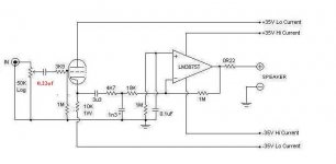
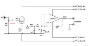
I would like to ask what is the purpose of the 1M resistor and 0.1uf cap from the non-inverting pin to ground?
I have seen other IGC circuits but they just have the non-inverting pin connected directly to ground.
I also noticed that building the circuit without the tube (just the IGC) still produced a turn-on thump .
.
I have tried NIGC and they are dead quiet at on and off. How home the IGC has a turn-on thump?
JojoD
I would like to ask what is the purpose of the 1M resistor and 0.1uf cap from the non-inverting pin to ground?
I have seen other IGC circuits but they just have the non-inverting pin connected directly to ground.
I also noticed that building the circuit without the tube (just the IGC) still produced a turn-on thump
.I have tried NIGC and they are dead quiet at on and off. How home the IGC has a turn-on thump?
JojoD
Attachments
- Status
- Not open for further replies.
- Home
- Amplifiers
- Chip Amps
- Tube with Power IC Output Stage - JLTi