hi,
the 0.1 cap is meant to put the non-inverting input at ground with respect to the inverting input...the 1Meg resistor is meant to bias the input so that output offset will remain quire low or close to zero...
many times you can get away without these components, you can experiment and find out...
still, you can make that resistor variable so that you trim the output offset voltage....
you can try leaving the tube powered on all the time and see if this helps...tube consume small power anyway....
Hi tony,
leaving the tube on will shorten it's life directly or indirectly right? anyway, with the tubes i will build a slow turn-on circuit that will slowly supply the power for the tubes.
my main concern is, without the tubes (circuit above with tube section removed) that circuit still has a turn on thump (none at turn off) while a NIGC has none whether on or off state.
i wonder why?
hi,
i know they seem to last forever. but some of our "audiophile" friends thinks otherwise.
anyway, the problem is not in the tube section, my question was why IGC has turn on thump while NIGC does not. 😀
JojoD
i know they seem to last forever. but some of our "audiophile" friends thinks otherwise.
anyway, the problem is not in the tube section, my question was why IGC has turn on thump while NIGC does not. 😀
JojoD
anyway, the problem is not in the tube section, my question was why IGC has turn on thump while NIGC does not.
My IGC doesn't have a turn on thump! 😉
I think that it may depend on the grounding arrangements. Try a straight wire from non-inverting pin to ground instead of a resistor (but recheck DC offset).
Nuuk said:
My IGC doesn't have a turn on thump! 😉
I think that it may depend on the grounding arrangements. Try a straight wire from non-inverting pin to ground instead of a resistor (but recheck DC offset).
That I will try,
Tnx Nuuk!
Using Joe's VBIGC circuit, I put a short between the 0.1uf // 1M and the turn-on thump was no more. BUT there was 0.2V dc offset in the output. 🙁
Nuuk,
Maybe I should try your feedback network values and see if they would make a lower dc offset.
JojoD
Nuuk,
Maybe I should try your feedback network values and see if they would make a lower dc offset.
JojoD
JojoD, please remember that with my VBIGC, I use a Velleman 4700 speaker protection circuit which doesn't connect the speakers for about 30 seconds after power up.
The IGC that I was referring to that doesn't have the turn-on thump is the OPA627 buffered version that uses different value components to the Joe Rasmussen circuit of the VBIGC.
The IGC that I was referring to that doesn't have the turn-on thump is the OPA627 buffered version that uses different value components to the Joe Rasmussen circuit of the VBIGC.
jojo,
another way would be to use a jfet muting ckt at the input of the gainclone chip set at about 15secs after power up...
of course, you can always use a speaker time delay relay at the output, but looks to me like your intent is not to go this route....as i am aware you know this trick.....
tony
another way would be to use a jfet muting ckt at the input of the gainclone chip set at about 15secs after power up...
of course, you can always use a speaker time delay relay at the output, but looks to me like your intent is not to go this route....as i am aware you know this trick.....
tony
Nuuk said:JojoD, please remember that with my VBIGC, I use a Velleman 4700 speaker protection circuit which doesn't connect the speakers for about 30 seconds after power up.
The IGC that I was referring to that doesn't have the turn-on thump is the OPA627 buffered version that uses different value components to the Joe Rasmussen circuit of the VBIGC.
joan2 said:jojo,
another way would be to use a jfet muting ckt at the input of the gainclone chip set at about 15secs after power up...
of course, you can always use a speaker time delay relay at the output, but looks to me like your intent is not to go this route....as i am aware you know this trick.....
tony
Nuuk, Tony,
Thanks for your patience guys. Tony, no can do for the relays, as shown, the case is too cramped already. Nuuk, I have seen your 627 buffered (frankly I have one too, thanks to you).
I will try and change feddback values and see if I can remove the turn on thump. The tube section has it's own soft start circuit and does not give any nasty thumps. 🙂 I hate turn on thumps! Hahaha


Oh btw, the tube section is a "tweaked" version. Using 240V as supply.
JojoD
JojoD818 said:Using Joe's VBIGC circuit, I put a short between the 0.1uf // 1M and the turn-on thump was no more. BUT there was 0.2V dc offset in the output. 🙁
You mean you shorted the non-inverting input to ground?
Try a lower resistor value instead, like 20K or 22K, and you might get no turn-on/turn-off thump and no DC offset.
Carlos
Nuuk, I have seen your 627 buffered (frankly I have one too, thanks to you).
So you have serial GC builders in PI too! 😀
carlmart said:
You mean you shorted the non-inverting input to ground?
Try a lower resistor value instead, like 20K or 22K, and you might get no turn-on/turn-off thump and no DC offset.
Carlos
Yup, that's what I did. Shorted the non-inverting pin to ground, huge offset... about 0.2V.
Thanks for the suggestion, I will try that asap.
Nuuk said:
So you have serial GC builders in PI too! 😀
You're speaking to one! Name it, I diy'd it! tda1552Q, tda1514, tda2030, tda2050, tda7293/4, opa541/8/9, lm383t, lm2005, lm1875, lm3875, lm3886.... and the list goes on... 😀
Now who says I love building GCs? 😀 😀 😀
My first ever GC amp was back in 1988, a chip used by Pioneer in their car stereo... the AN-214 a 5.6W chipamp. 🙂 Used it for a school project though. 😀
Me too
Hi
This is my first posting, out of Switzerland.
I successfully built my first tube buffered gainclone, based on the schematics from Joe Rasmussen (Thanks, Joe!).
The main differences in my implementation are:
- 2x18V 160VA
- startup delay with NE555 (to avoid startup transient from the tube)
- ECC82, AC filament
- no filter at the chip input
- Cc 4,3uF, Ri 2.2K, Rf 56K
- different psu-bypass (2x1000uF, 2x1uF, 2x0,1uF, 100uF)
- zobel network at the output (0,1uF / 10R)
It is a great amp and for some music (for example Pink Floyd) I prefer it over my 300B.
Franz
P.S.
Next time, I would design the pcb different and use both sides of it.
Attachments
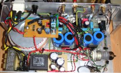
My real first tube GC
This was my real first tube-gc: an ECC82 as cathode grounded
system for the voltage gain, little voltage gain from the chip.
Actually, I reduce the gain from the valve by two resistors by the anode, because the overall gain is too high.
I want to try unity gain or feedback to the cathode.
The layout inside is not as flexible, as I used some experimental board and attached 1M feedback resistors in a very hidden place
This amp sounds very nearby a very good tube amp, but I have some Bias on the output (<20mV).
Franz
Attachments
Soon
I will show you my schemas, as soon as I don't change them...
Actually, I still work on both amps and add daily some changes.
Today I worked on the amp with the tube gainstage. I made a new pcb for it and tried the unity gain version.
Franz
I will show you my schemas, as soon as I don't change them...
Actually, I still work on both amps and add daily some changes.
Today I worked on the amp with the tube gainstage. I made a new pcb for it and tried the unity gain version.
Franz
the schematics of my amps
This are the actual schematics of my gainclones:
http://mypage.bluewin.ch/gysiaudiophil/Schemaanodenfolger.GIF
http://mypage.bluewin.ch/gysiaudiophil/Schemakathodenfolger.gif
I wrote some text in german, but I will translate it (later) if requested.
http://f23.parsimony.net/forum45451/messages/88893.htm
Franz
Re: the schematics of my amps
Hi Franz
Looks like you are having fun. I am sure that you will describe the difference between the two circuits, sound wise.
-----------------------------------------------------------------------------------------------------------
Did you get away with only +/- 35V on the ECC-82 shown below?
-----------------------------------------------------------------------------------------------------------
Also I note that you are using 250V with the split anode version. May I also make a suggestion, remove the 100uF cathode by-pass electrolytic?
Are you familiar with the Lynn Olson 'Loop Distortion' lecture found at http://www.nutshellhifi.com/library/Tube_Fest_Talk.html
He wrote this after an article describing my all-tube Isolated Loop Amplifier (ILA) was passed on to him.This, the ILA, is a power amplifier with zero 'Loop Distortion.' If you read his link, then you will realise that electrolytic is not desirable. Removing it will drop in AC gain (local degeneration), but lower gain here is really what we want. The split anode may not need to be split? May I suggest you try it and report back.
Regards
Joe R.
Franz G said:This are the actual schematics of my gainclones:
http://mypage.bluewin.ch/gysiaudiophil/Schemaanodenfolger.GIF
http://mypage.bluewin.ch/gysiaudiophil/Schemakathodenfolger.gif
I wrote some text in german, but I will translate it (later) if requested.
http://f23.parsimony.net/forum45451/messages/88893.htm
Franz
Hi Franz
Looks like you are having fun. I am sure that you will describe the difference between the two circuits, sound wise.
-----------------------------------------------------------------------------------------------------------
Did you get away with only +/- 35V on the ECC-82 shown below?
An externally hosted image should be here but it was not working when we last tested it.
-----------------------------------------------------------------------------------------------------------
Also I note that you are using 250V with the split anode version. May I also make a suggestion, remove the 100uF cathode by-pass electrolytic?
An externally hosted image should be here but it was not working when we last tested it.
Are you familiar with the Lynn Olson 'Loop Distortion' lecture found at http://www.nutshellhifi.com/library/Tube_Fest_Talk.html
He wrote this after an article describing my all-tube Isolated Loop Amplifier (ILA) was passed on to him.This, the ILA, is a power amplifier with zero 'Loop Distortion.' If you read his link, then you will realise that electrolytic is not desirable. Removing it will drop in AC gain (local degeneration), but lower gain here is really what we want. The split anode may not need to be split? May I suggest you try it and report back.
Regards
Joe R.
- Status
- Not open for further replies.
- Home
- Amplifiers
- Chip Amps
- Tube with Power IC Output Stage - JLTi