Joe Rasmussen said:
Check against the posted diagrams, for errors and also to improve your wiring. You may have a severe stability problem or wiring problem. Also check your filament supply while at it.
Joe R.
Thanks Joe for taking the time. I have checkd all wirings and they are good. I found that my heater voltage is only 4.4VDC!
I have rectified the problem and now the amp plays beautifully. Thanks for a great DIY amp!
Best Regards,
JojoD
Member
Joined 2002
i have 6 of these LM-3875 chips i wonder if Dave ( planet10 ) would have 2 of these tubes it could be another project for me to play with..
Suitable Cap for LPF
Hi All,
I know that the value of the "1n3" cap in the LPF can be changed to suit different systems and personal tastes, but what kind of cap are people using here? I had MKC type suggested to me, but these seem to be hard to get a hold of, I don't think they are still being produced, how about MKP or MKS? I was also looking at Panasonic ECHS. Anybody have a source for MKC? Any other suggestions?
Thanks
I know that the value of the "1n3" cap in the LPF can be changed to suit different systems and personal tastes, but what kind of cap are people using here?
A small polystyrene or polypropylene is ideal. I get mine from Farnell here in the UK so I can't advise you on a local source where you are.
What changes are needed to make a VIGC a V-NIGC ?
A few changes in values are required but I have tried to keep them as similar as possible to VIGC. Keep in mind that this hasn't been built yet, but I don't foresee any real problems. But it probably makes sense for someone with previous experience, who has already done a VIGC using earlier the earlier values, make convertion and then report back.
Again the usual recommendation to tweak the 1n3* value.
Joe R.
A few changes in values are required but I have tried to keep them as similar as possible to VIGC. Keep in mind that this hasn't been built yet, but I don't foresee any real problems. But it probably makes sense for someone with previous experience, who has already done a VIGC using earlier the earlier values, make convertion and then report back.
An externally hosted image should be here but it was not working when we last tested it.
Again the usual recommendation to tweak the 1n3* value.
Joe R.
Well, I would love to have a go at the above schematic as I am about to build a NIGC. Unfortunately I just don't have the time/money to change my plans to a VBNIGC at this moment. I'll certainly give it a go in a couple of months.
BTW, did I mention that I tried a range of four reasonable quality polystyrene LPF caps, between 680pF and 2n2? I hardly notioed any difference in the sound between the 680pF, 1n0 and 1n3 caps. If anything the 680pF sounded a touch softer (and I mean a touch). The 2n2 cap however seems to give more sibilance to vocals and cymbals but I actually prefer this as it gives a little extra life to the sound - it's not problematic sibilance, just more realistic.
However, these results are through my very cheap and very warm sounding Wharfedale Lintons (1970s) as my lovely TLs were fried in an unfortunate DC offset accident. However, I have stuck to the 2n2 cap as I prefer the brighter top end with the warmer speakers. Like you say Joe, it is very much a matter of set-up. 😉
Just some additional construction thoughts:
1) This circuit is not strictly U-G (Unity Gain) @ DC, hence any DC imbalance at the input is likely to be amplified at the output as DC Offset.
2) To make it U-G, use a largish cap, but not electrolytic cap, should be inserted between 18K connected to the (-) input and ground. I would be inclined to use 10uF. But also inclined to avoid using it at all.
3) Thorsten's most recent IGC that I have seen does not look strictly not U-G either (the earlier one is as well as the VIGC). Low DC values and well balanced inputs may avoid using U-G cap. It is worth a try. In Thorsten's his gain is a lot lower and DC is potentially amplified less. The 820K/18K feedback ratio gives a gain of 46 (33dB) and this could be a problem without the additional U-G cap.
4) It might be a good idea, if no U-G cap is to be used, to put another 820K resistor in parallel with the input 18K, since in DC terms the 820K/18K feedback resistors are also in parallel (so both inputs sees 17K613 @ DC). The difference between 18K and 17K613 x 46 could be significant?
So, as said, this is yet to be constructed and sussed out. Best to be tried by a current experienced VIGC constructor?
Joe R.
An externally hosted image should be here but it was not working when we last tested it.
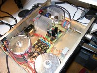
That's what I built mostly basing on Joe Rasmussen scheme.
As you see I used 2 toroidal transformers for LM3785 TF. 150-200 VA each. Two rectifier bridges per channel. I've got about 32V going to chips. There is only one tube Reflector 6922 working as buffer. Separate transformers for filament 6.2V and plates 45V. Attenuator 10K. This is of course LM3875 inverted topology with 1n6 cap filter. Ground point is beetwen the chips connected to chassis. Most of the parts are a little better than Radioshack type. It worked right away. I was suprised by very low offset only 2mV and 5mV. There is no hum or hiss and total silence with no signal. Filament transformer is funny small but that's what I had. I built power supply stage and realized that I don't have right transformer. Later I found nice 3A 7v-0-7v transformer but I'm not quite sure how to implement it. 14V+ is killing 7808 even with that heatsink. Some help appreciated.
Need to get RCA jacks, maybe better signal wires.
Sound ....
I built many Gainclones: inverted, non-inverted, buffered with buf634 and tube buffered is the best at least to my taste. That little addition of tube magic works excellent.
Thank You Joe Rasmussen for the scheme and others for being on the forum I couldn't build that amp without.
Attachments
thomashek said:That's what I built mostly basing on Joe Rasmussen scheme.
Sound ....
I built many Gainclones: inverted, non-inverted, buffered with buf634 and tube buffered is the best at least to my taste. That little addition of tube magic works excellent.
Thank You Joe Rasmussen for the scheme and others for being on the forum I couldn't build that amp without.
Hey, this is the best part, just great! Bet this is your first tube project? If so, welcome to the club.
Joe R.
Damn Joe. You got me.
That's my first tube project. I'm complete greenhorn in that field but I'd like to explore more and more. To my satisfaction my first project works really well, maybe too well because I feel audio tube desease growing inside me.
Thanks
By the way..... Can I somehow, safely implement that 3A 7-0-7V transformer for the heater ?
Hi,
You can: 7 * 1.41 = 9.87 > 7806 = 6V out or LM317 adj. to 6.3VDC or low voltage drop reg.with 6V out.
BTW, hope to see you in the "Tubes" section soon....
Cheers,😉
By the way..... Can I somehow, safely implement that 3A 7-0-7V transformer for the heater ?
You can: 7 * 1.41 = 9.87 > 7806 = 6V out or LM317 adj. to 6.3VDC or low voltage drop reg.with 6V out.
BTW, hope to see you in the "Tubes" section soon....
Cheers,😉
thomashek said:
Damn Joe. You got me.
That's my first tube project. I'm complete greenhorn in that field but I'd like to explore more and more. To my satisfaction my first project works really well, maybe too well because I feel audio tube desease growing inside me.
And that was the whole idea. We have created a new bunch of tube DIY heads out there and now they may well be emboldened to reach further. They now have a handle on such mysteries as filament supplies (that is what makes to tube glow). This is us older tube heads handing on the baton.
thomashek said:
By the way..... Can I somehow, safely implement that 3A 7-0-7V transformer for the heater ?
Certainly enough current, but maybe treat as a AC 14V secondary? Converting that to DC and getting down to 6.3V DC could mean a lot of heat to dissipate?
Anyone else got any ideas? This is always about issues of implementation.
Joe R.
Hi,
True but he doesn't have to use the full secondary winding:
0-7VAC would be just about O.K. with a 78xx but a low voltage drop type would be better.
If you use the full secondary, full wave bridge rectified you end up with about 19 VDC, add a reg and use a 12DJ8 iso a 6DJ8 for instance.
Also using the entire secondary winding full wave (not Graetz bridge) into a capacitive load again, you'd have about 9.5 VDC, add the reg and you're done.
Cheers,😉
Certainly enough current, but maybe treat as a AC 14V secondary? Converting that to DC and getting down to 6.3V DC could mean a lot of heat to dissipate?
True but he doesn't have to use the full secondary winding:
0-7VAC would be just about O.K. with a 78xx but a low voltage drop type would be better.
If you use the full secondary, full wave bridge rectified you end up with about 19 VDC, add a reg and use a 12DJ8 iso a 6DJ8 for instance.
Also using the entire secondary winding full wave (not Graetz bridge) into a capacitive load again, you'd have about 9.5 VDC, add the reg and you're done.
Cheers,😉
fdegrove said:Hi,
0-7VAC would be just about O.K. with a 78xx but a low voltage drop type would be better.
OK. I threw the values into Duncan's PSU Designer 2 program, with 4007 bridge and 10,000uF (you need a lot of capacitance at low V). Got 7.8V but the ripple dips down to 6.6V - and up to 9V.
Have you tried this little piece of software?
Joe R.
Joe Rasmussen said:
OK. I threw the values into Duncan's PSU Designer 2 program, with 4007 bridge and 10,000uF (you need a lot of capacitance at low V). Got 7.8V but the ripple dips down to 6.6V - and up to 9V.
Have you tried this little piece of software?
Joe R.
Oops! I take that back. The 10,000uF ESR was set to 2 Ohm, reset it to 0.2 Ohm - still got 7.8V but ripple from 7.6V and 8.2V - but still not good enough IMO. If using a 7806 (most 6922 will do OK on that), is 1.6V enough to prevent the 6V DC coming out not having little negative going dips 100 times per second?
I tried 9V AC, 2200uF w/bridge. Got 10.4V and ripple 9.7V to 11V - I reckon that is what it needs. The key thing is to look at the bottom of the ripple and take that as being the true voltage pre reg. The DC voltmeter only measures the 'average' volts. Now set the meter to DC and measure the ripple. Multiply that by 1.4 times and take away from the average DC measurement. Now take away the 78xx value and you have the clean DC across the regulator. What does this need according to the specs? 2V? 3V? Or whatever. Does that make sense?
I used 310mA to simulate the filament load. BTW, in our VSE FVP Phono preamp, the filament supply, it has 18V AC, bridge and 2200uF. The average volts never reach 1.41 times (25.3v). The load is 650mA @ 15V (reg'd) and we get about 22V and 0.7V RMS ripple. I put that into Duncan's simulator and got the same result as in the real world. Not a bad program.
Joe R.
Sorry for really late reply.
I tried that 7-0-7 transformer for filament. I used only one half of windings so needed to add lot of capacitance and then LM317 to regulate voltage 6.3v. However I feel a little discomfort or in other words, lack of knowledge. The tube draws enough current so the measured voltage acros regulator drops a "bit". Instead of 6.3v I set there is about 5.5v. Shouldn't I set voltage while tube works ?
Thanks
Hi,
Yes, you should have the load in place.
Just put the tube in and try to set the voltage for 6V or 6.3V if possible.
Cheers,😉
Shouldn't I set voltage while tube works ?
Yes, you should have the load in place.
Just put the tube in and try to set the voltage for 6V or 6.3V if possible.
Cheers,😉
Hi,
This question may be stupid as i never have tube experience.
Just cann't help wondering, is it reasonalbe if i regulate the +/- 35V tube power? Something like 30Vac -> LM317 (or LT1085) -> 35Vdc. I noticed the current is just a few mA and a simple 3-terminal regulator should do the job.
This question may be stupid as i never have tube experience.
Just cann't help wondering, is it reasonalbe if i regulate the +/- 35V tube power? Something like 30Vac -> LM317 (or LT1085) -> 35Vdc. I noticed the current is just a few mA and a simple 3-terminal regulator should do the job.
Newbie said:is it reasonalbe if i regulate the +/- 35V tube power?
Yes it does... Joe mentions that he uses a version of the SuperReg in his commercial product...
dave
- Status
- Not open for further replies.
- Home
- Amplifiers
- Chip Amps
- Tube with Power IC Output Stage - JLTi