results LM3875 versus LM1875
I certainly prefer the 3875. The 1875 sounds brighter, faster and thinner with less deep bass. It's quite amusing that the idling current of the smaller chip is so much higher.
peter
If LM1875 is considered similar to LM3875 I’ve got one from Multisim. In fact these are different chips, among the other things, as just Peter noted, its idling current is twice higher than 3875’s. Nevertheless, in this lack of appropriate spice models it can be useful. But I don’t know if it is OK to post it publicly.Joe Rasmussen said:Does anyone know of a Spice model for LM38xx or similar?
Btw, I never understood why moderators ignored many suggestions for making of separate spice or generally CAD forum. There is quite a lot of interest for this here.
Pedja
Tor M said:ARRGHH!
Sorry for bothering everybody, but now I really need some help.
My new 6922 suddenly died, this time in the right channel. It`s playing half volume like the last one did in the left channel.
My current setup is like Joe`s schematics but with the pi filter with 165 ohm resistor and Fc 1200uF capasitor.
The filament votage is 6.3 V using 15VA 2 X 9 V, one bridge, lm 317 using a 2k multiturn pot and a 330 ohm resistor to set voltage at exactly 6.3 V
The cathodes are -42,2V and anodes are +42,8V.
I hope I can get new tubes on the 90 days guarante.
The electricity in my house are kind of rotten, and I can hear power transients in the speakers when somebody is turining a light swich.
My cdplayer has 10 mV of dc on the outputs.
Anybody have any Idea why the tubes are getting damaged?
(If I could put those two tubes together I now would have one working😉 )
Does your grid bias, relative to the cathode, measure the same for both halves of the tube?
Thanks for answering.
You have to excuse my lack of knowlage, this is my first time using tubes. I`m reading an old electronic book from 1955 at the moment to learn about tubes.
So here is my stupid question:
How do I measure this. It`s probably plain logic, but................😕
Tor Martin🙂
You have to excuse my lack of knowlage, this is my first time using tubes. I`m reading an old electronic book from 1955 at the moment to learn about tubes.
So here is my stupid question:
How do I measure this. It`s probably plain logic, but................😕
Tor Martin🙂
Tor M said:Thanks for answering.
How do I measure this. It`s probably plain logic, but................😕
Tor Martin🙂
uhhmmm...errrr... when it involves the use of dual power rails, I don't know. With a "normal" supply, you just measure the difference in potential between cathode and grid(thru ground). With the cathode being connected to -35V, and not directly to ground...uhhmmm
...someone please jump in here and get me outta this mess

my original thought was that when running a tube at such a low B+, any differences in bias would have a greater effect on voltage swing...don't know if that holds up or not...
HELP!
Member
Joined 2002
pedroskova said:...someone please jump in here and get me outta this mess
HELP!
Hi,
Tor
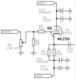
First, make sure that grid DC voltage to ground is 0V when your source is connected to input (this is very important).
Second, measure DC voltage chatode-ground. This voltage must be higher than 0V.
Take a look at my readings in the picture below.
Regards
Attachments
moamps said:
Hi,
Tor
First, make sure that grid DC voltage to ground is 0V when your source is connected to input (this is very important).
Second, measure DC voltage chatode-ground. This voltage must be higher than 0V.
Take a look at my readings in the picture below.
Regards
Thanks moamps!!
The weather is beautifully here with 30 degrees C and this is exeptional to be on the west coast of Norway. So I`ll have to waith untill tonight to do some measuring, the beach is calling!
Did you mean measure DC voltage cathode-grid(not cathode to ground) to be higher than 0V, to make sure grid is negative compared to cathode?
Thanks for help.
Tor Martin🙂
Tor M said:Did you mean measure DC voltage cathode-grid(not cathode to ground) to be higher than 0V, to make sure grid is negative compared to cathode?
Yes, grid must be negative compared to chatode.
If here is grid at ground, then chatode-grid voltage mean same like chatode-ground voltage.😉
What is the sea temperature?

Regards
Progress Continues...
Well as you know I have been trying to trouble shoot my humming issues and ended up by-passing the tube part of the circuit, well the hum was still there. So now I am at a loss, because I am using the exact same ground scheme I used on my minimal gc which is absolutely quiet. The only difference in the two is that I am using two e- core transformers in the hybrid version, instead of one toroid in the minimal gc.
Another weird thing is the hum is more like poor tv reception and when I get my hand close to the 3.3uf input caps the hum gets extremley loud. I'll try replacing the e-cores with toroids and see how it sounds.
The saga continues ...Lee
Well as you know I have been trying to trouble shoot my humming issues and ended up by-passing the tube part of the circuit, well the hum was still there. So now I am at a loss, because I am using the exact same ground scheme I used on my minimal gc which is absolutely quiet. The only difference in the two is that I am using two e- core transformers in the hybrid version, instead of one toroid in the minimal gc.
Another weird thing is the hum is more like poor tv reception and when I get my hand close to the 3.3uf input caps the hum gets extremley loud. I'll try replacing the e-cores with toroids and see how it sounds.
The saga continues
...LeeThe only difference in the two is that I am using two e- core transformers in the hybrid version, instead of one toroid in the minimal gc.
That may be the probelm! As I understand it, the magnetic fields of the E-core transformers radiate sideways while those from the torroidals go vertically, ie through the top and bottom of the housing but not into it.
Did you connect the case to the ground ? Try it, with 220 ohm//220 nF in series...
The only metal in the case are the two 6"x6" heatsinks. I do get some buzz when I touch them so I will see if grounding those helps.
Thanks...Lee
In that case I would advise to shield the case by foil. The opamp circuits very easily pick up noise!
Fedde
Fedde
Re: Progress Continues...
Hi,
In the picture you posted, I saw that transformers are far away from amps and the tube so I don't think that the problem is with transformers noise. IMHO, things won't be better if e-cores are replaced with toroids.
My suggestion is:
Disconnect the tube buffer, check amps wiring and make sure that amps work OK without buffer, that there's no noise. Turn the tube buffer on without connecting it to the amps and check all connections. Measure Vripple on tube power supplies (multimeter on AC volt range). Connect, say, one headphone driver to the output of the buffer (after block condenser). If you can hear hum, something is wrong (for example, you may have forgotten to implement CRC network for tube buffer supply). Once your buffer is working correctly, connect the output of the buffer to the input of the amp with a single coax audio cable. Once you get this setup working properly, you should try out other arrangements and connections.
Regards
king30 said:Well as you know I have been trying to trouble shoot my humming issues and ended up by-passing the tube part of the circuit, well the hum was still there. So now I am at a loss, because I am using the exact same ground scheme I used on my minimal gc which is absolutely quiet. The only difference in the two is that I am using two e- core transformers in the hybrid version, instead of one toroid in the minimal gc.
Hi,
In the picture you posted, I saw that transformers are far away from amps and the tube so I don't think that the problem is with transformers noise. IMHO, things won't be better if e-cores are replaced with toroids.
My suggestion is:
Disconnect the tube buffer, check amps wiring and make sure that amps work OK without buffer, that there's no noise. Turn the tube buffer on without connecting it to the amps and check all connections. Measure Vripple on tube power supplies (multimeter on AC volt range). Connect, say, one headphone driver to the output of the buffer (after block condenser). If you can hear hum, something is wrong (for example, you may have forgotten to implement CRC network for tube buffer supply). Once your buffer is working correctly, connect the output of the buffer to the input of the amp with a single coax audio cable. Once you get this setup working properly, you should try out other arrangements and connections.
Regards
Did some more testing and made some configuraton changes on my system (grounding the heatsinks, moving to a toroid instead of e-core for the chips) to try and get rid of some hum.
I know have one channel that is almost quiet and one that is noticebly louder. Well in doing some trouble shooting I changed the connections on the heater ps swapping the +/- and found that the hum carried to the other speaker with the negative connection. I only have two 100uf caps on the rails and will see if upgrading to 4-1000uf or 2200uf caps helps at all.
Lee
Hi,
100µF is certainly not enough but before you add bigger capacitance you could try tightly twisting both heater wires together.
Than push them close to the bottom of the housing and well away from any other wiring.
What you're hearing now is quite likely 120Hz hum.
Hope this helps,😉
I only have two 100uf caps on the rails and will see if upgrading to 4-1000uf or 2200uf caps helps at all.
100µF is certainly not enough but before you add bigger capacitance you could try tightly twisting both heater wires together.
Than push them close to the bottom of the housing and well away from any other wiring.
What you're hearing now is quite likely 120Hz hum.
Hope this helps,😉
king30 said:I only have two 100uf caps on the rails and will see if upgrading to 4-1000uf or 2200uf caps helps at all.
Do you have a resistor between the caps, for a CRC filter? If not, that should help.
Hi,
I assumed one was there already since the rectified voltage would be too high in most cases.
One other thing to keep track off is the DC voltage itself, it should be close to 6.3VDC at the heaters.
When you add extra caps this voltage may rise above 6.3V depending on what was there before.
Cheers, 😉
Do you have a resistor between the caps, for a CRC filter? If not, that should help.
I assumed one was there already since the rectified voltage would be too high in most cases.
One other thing to keep track off is the DC voltage itself, it should be close to 6.3VDC at the heaters.
When you add extra caps this voltage may rise above 6.3V depending on what was there before.
Cheers, 😉
- Status
- Not open for further replies.
- Home
- Amplifiers
- Chip Amps
- Tube with Power IC Output Stage - JLTi