Try throwing the 8s on a baffle (even just a big piece of cardboard... you might be surprised
I spent all Saturday listening to the el84 SE amp using the original speakers. I *am* surprised. They are currently on the exsiting baffle but now I need to make an enclosure.
I'm currently rebuilding the amp similar to this thread.
1/2 of a 12at7 driver into a el84. I only had to buy two 470k resistors 🙂.
rick
rickl said:
...listening to the el84 SE amp using the original speakers. I *am* surprised. They are currently on the exsiting baffle but now I need to make an enclosure.
...
rick
My first thrift store tube amp was a mono unit from an old console record player. I too was surprised at the quality of the sound with the 15" woofer and 3" tweeter. Very natural and detailed midrange, decent bass (but without "punch") and an OK high end which got better when I replaced the cap in the XO.
However when I tried to put the speaker in an enclosure it killed the sound. I know these old drivers were designed for use in an enclosure without a back but I was surprised at just how terrible the sound became when enclosed, regardless of the size of port I tried.
I ended up building a cabinet with an open back quite a bit larger than the original and added a 1/4" jack and an RCA connector for my oldest son to use as a guitar amp. It sounds great with a CD player connected to the RCA and pretty darn good with his guitars.
Just be careful with the enclosure and you should end up with pretty decent sound.
Sherman,
Thanks for the note on enclosures. I'm currently rebuilding the amp and once I get that done, I'll focus on the speakers. My guess I'll just build only back 'boxes' and set them on the shelf.
Thanks again,
rick
Thanks for the note on enclosures. I'm currently rebuilding the amp and once I get that done, I'll focus on the speakers. My guess I'll just build only back 'boxes' and set them on the shelf.
Thanks again,
rick
Need advice .. 50EH5 Amp
Greetings,
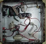
I need some advice and pointers to finish up a 50EH5 "spud" amp. Underside picture attached.
The datasheet for the 50EH5 can be found at:
http://www.mif.pg.gda.pl/homepages/frank/sheets/093/5/50EH5.pdf
Dave mapped the console that the parts came from:
http://www.diyaudio.com/forums/attachment.php?s=&postid=563745&stamp=1107083701
I am generally following this circuit:
http://www.mif.pg.gda.pl/homepages/frank/short/001/5/50EH5.gif
I will not use a DC blocking cap. The heaters are 50VAC. Going to DC heaters is possible.
I need some help with grounding. I have made this with a 3 prong outlet, so I have taken the ground from the outlet to the chassis. The AC from the mains transformer is to the heaters and to a 4XUF4006 bridge into a 70ohm, 220uF, 220ohm 470uF, 22ohm, 470uF supply.
Should the speaker negative and RCA negative go to the chassis?
What about the DC negative ... should that also go to the chassis?
Regards,
Gio.
Greetings,
I need some advice and pointers to finish up a 50EH5 "spud" amp. Underside picture attached.
The datasheet for the 50EH5 can be found at:
http://www.mif.pg.gda.pl/homepages/frank/sheets/093/5/50EH5.pdf
Dave mapped the console that the parts came from:
http://www.diyaudio.com/forums/attachment.php?s=&postid=563745&stamp=1107083701
I am generally following this circuit:
http://www.mif.pg.gda.pl/homepages/frank/short/001/5/50EH5.gif
I will not use a DC blocking cap. The heaters are 50VAC. Going to DC heaters is possible.
I need some help with grounding. I have made this with a 3 prong outlet, so I have taken the ground from the outlet to the chassis. The AC from the mains transformer is to the heaters and to a 4XUF4006 bridge into a 70ohm, 220uF, 220ohm 470uF, 22ohm, 470uF supply.
Should the speaker negative and RCA negative go to the chassis?
What about the DC negative ... should that also go to the chassis?
Regards,
Gio.
Attachments
Re: Need advice .. 50EH5 Amp
If you aren't using any feedback you can just float the speaker outputs. As to wiring schemes... do a serach on star grounding... to much material to go into here, but as a simplification all the signal grounds should go to one point, all the PS grounds to a different point, then these 2 should be wired together & to the chassis (often thru a very small cap)
dave
GG said:Should the speaker negative and RCA negative go to the chassis?
What about the DC negative ... should that also go to the chassis?
If you aren't using any feedback you can just float the speaker outputs. As to wiring schemes... do a serach on star grounding... to much material to go into here, but as a simplification all the signal grounds should go to one point, all the PS grounds to a different point, then these 2 should be wired together & to the chassis (often thru a very small cap)
dave
Re: Re: Need advice .. 50EH5 Amp
Thanks .. I was a little worried about connecting the AC ground to the DC negative. I will worry about snubber, coupling and bypass caps later.
Dave, in your proposed minimalistic 50EH5 SE amp, you have deleted the capacitor which is parallel to the 62ohm resistor. What is the purpose of this capacitor? Typically I have seen a low voltage 100uF electroylitc there.
planet10 said:
If you aren't using any feedback you can just float the speaker outputs. As to wiring schemes... do a serach on star grounding... to much material to go into here, but as a simplification all the signal grounds should go to one point, all the PS grounds to a different point, then these 2 should be wired together & to the chassis (often thru a very small cap)
dave
Thanks .. I was a little worried about connecting the AC ground to the DC negative. I will worry about snubber, coupling and bypass caps later.
Dave, in your proposed minimalistic 50EH5 SE amp, you have deleted the capacitor which is parallel to the 62ohm resistor. What is the purpose of this capacitor? Typically I have seen a low voltage 100uF electroylitc there.
Re: Re: Re: Need advice .. 50EH5 Amp
That is called the cathode bypass. It shunts AC around the DC bias resistor. With it removed the signal modulates the bias giving what is called degenerative feedback. Distrotion is theoretically lowered, but stage gain will go down and the plate impedance will go up (the later can be compensated for somewhat by attaching higher impedance speakers -- the gain requires more grunt going in). I don't know whether it will work out in this case, but the appeal of using as a few parts as possible is driving the concept.
dave
GG said:in your proposed minimalistic 50EH5 SE amp, you have deleted the capacitor which is parallel to the 62ohm resistor. What is the purpose of this capacitor? Typically I have seen a low voltage 100uF electroylitc there.
That is called the cathode bypass. It shunts AC around the DC bias resistor. With it removed the signal modulates the bias giving what is called degenerative feedback. Distrotion is theoretically lowered, but stage gain will go down and the plate impedance will go up (the later can be compensated for somewhat by attaching higher impedance speakers -- the gain requires more grunt going in). I don't know whether it will work out in this case, but the appeal of using as a few parts as possible is driving the concept.
dave
Those capacitors in the ceramic tubes are usually just wax paper caps. They tend to absorb moisture from the air and get leaky. So they are not as good as they look  However, if you use them across low value resistors (say below 50K) the leakage resistance would be swamped out. DO NOT use them to couple from a plate circuit to a grid circuit, or else that grid will get pulled positive and make for orange plates and overloaded output transformers and power supplies and other undesired disasters....😱
However, if you use them across low value resistors (say below 50K) the leakage resistance would be swamped out. DO NOT use them to couple from a plate circuit to a grid circuit, or else that grid will get pulled positive and make for orange plates and overloaded output transformers and power supplies and other undesired disasters....😱Re: Re: Re: Re: Need advice .. 50EH5 Amp
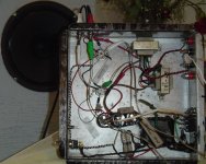
OK. It looks like you can get away without that capacitor. Right now I have it going with only the 62ohm on the cathode.
I checked voltages... 52VAC on the heaters, I think that is close enough. The plate and grid voltage is ~118 to 123V .. that is about 6-8V more than I was shooting for. Should I drop the voltage down or is this fine?
The sound ... very good. There is more bass than what I was expecting from those little OTs, but you do not get full bass extension. The midrange and highs are very strong...I am rather impressed. Power as expected is limited, a little over 1 watt. This looks like it will be a good canidate for a head amp or as part of a bi-amp system driving a high efficiency supertweeter.
Also to my suprise is that there is no audible hum. I was concerned that the 50VAC heaters would be a problem ... they are not, so the heaters will stay AC.
I will try capacitors on the cathode and see if that makes a difference....I prefer not to use a capacitor if possible. I also will try a resistor between the input and ground.
😀
planet10 said:
That is called the cathode bypass. It shunts AC around the DC bias resistor. With it removed the signal modulates the bias giving what is called degenerative feedback. Distrotion is theoretically lowered, but stage gain will go down and the plate impedance will go up (the later can be compensated for somewhat by attaching higher impedance speakers -- the gain requires more grunt going in). I don't know whether it will work out in this case, but the appeal of using as a few parts as possible is driving the concept.
dave
OK. It looks like you can get away without that capacitor. Right now I have it going with only the 62ohm on the cathode.
I checked voltages... 52VAC on the heaters, I think that is close enough. The plate and grid voltage is ~118 to 123V .. that is about 6-8V more than I was shooting for. Should I drop the voltage down or is this fine?
The sound ... very good. There is more bass than what I was expecting from those little OTs, but you do not get full bass extension. The midrange and highs are very strong...I am rather impressed. Power as expected is limited, a little over 1 watt. This looks like it will be a good canidate for a head amp or as part of a bi-amp system driving a high efficiency supertweeter.
Also to my suprise is that there is no audible hum. I was concerned that the 50VAC heaters would be a problem ... they are not, so the heaters will stay AC.
I will try capacitors on the cathode and see if that makes a difference....I prefer not to use a capacitor if possible. I also will try a resistor between the input and ground.
😀
Attachments
Re: Re: Re: Re: Re: Need advice .. 50EH5 Amp
I wouldn't woory too much
You go have a grid leak resistor there already don't you?
dave
GG said:I checked voltages... 52VAC on the heaters, I think that is close enough. The plate and grid voltage is ~118 to 123V .. that is about 6-8V more than I was shooting for. Should I drop the voltage down or is this fine?
I wouldn't woory too much
I also will try a resistor between the input and ground.
You go have a grid leak resistor there already don't you?
dave
Re: Re: Re: Re: Re: Re: Need advice .. 50EH5 Amp
No. All I have is the 62ohm resistor. What is the purpose of a resistor between the line in and ground?
planet10 said:
You go have a grid leak resistor there already don't you?
dave
No. All I have is the 62ohm resistor. What is the purpose of a resistor between the line in and ground?
Re: Re: Re: Re: Re: Re: Re: Need advice .. 50EH5 Amp
The grid leak ties the grid to ground (since almost no current flows thru it). Without it you aren't developing the proper bias... the last time i forgot the grid leak i quickly let the smoke out of a few things. I'm surprised the amp works without it -- or have you put a pot on the input (which would then be your grid-leak)?
dave
GG said:No. All I have is the 62ohm resistor. What is the purpose of a resistor between the line in and ground?
The grid leak ties the grid to ground (since almost no current flows thru it). Without it you aren't developing the proper bias... the last time i forgot the grid leak i quickly let the smoke out of a few things. I'm surprised the amp works without it -- or have you put a pot on the input (which would then be your grid-leak)?
dave
Re: Re: Re: Re: Re: Re: Re: Re: Need advice .. 50EH5 Amp
Yes, I had a pot on. What sort of damage could the lack of a grid leak cause?
planet10 said:
The grid leak ties the grid to ground (since almost no current flows thru it). Without it you aren't developing the proper bias... the last time i forgot the grid leak i quickly let the smoke out of a few things. I'm surprised the amp works without it -- or have you put a pot on the input (which would then be your grid-leak)?
dave
Yes, I had a pot on. What sort of damage could the lack of a grid leak cause?
Re: Re: Re: Re: Re: Re: Re: Re: Re: Need advice .. 50EH5 Amp
The pot acts as the grid leak -- it is a resistor from grid to ground. You probably have a 100k, higher would be better.
dave
GG said:
Yes, I had a pot on. What sort of damage could the lack of a grid leak cause?
The pot acts as the grid leak -- it is a resistor from grid to ground. You probably have a 100k, higher would be better.
dave
50EH5 Cathode Bypass
I have experimented with and without a cathode bypass. Without the bypass, there is a clear loss of power. Connected to a Radio Shack 40-1271 on an open baffle, I measure 80dB with a 100uF bypass and only 74dB without a bypass at a distance of 1m. The 40-1271 are rated at 88dB, so my CDP is not providing enough drive to get the maximum output of about 1.3W.
In addition to the clear loss of power without the cathode bypass, there is a loss of depth to bass and mid-bass. However, the mid-range and high frequency response seem to be unaffected. This was confirmed by driving only a tweeter. I will try this again when I get my hands on a nice super tweeter.
If the intended use of the amp is only to drive a midrange/tweeter, you can likely get away without a cathode bypass.
I also experimented with the size of the cathode bypass. 82uF does not quite get you there and there is no advantage in going larger than 100uF. Unfortunately, electrolytic seems to be the only practical choice at 100uF.
I also experimented with the grid leak. When connected to a 100k pot, there is no noticable differnence with additional resistance.
Gio.
planet10 said:
That is called the cathode bypass. It shunts AC around the DC bias resistor. With it removed the signal modulates the bias giving what is called degenerative feedback. Distrotion is theoretically lowered, but stage gain will go down and the plate impedance will go up (the later can be compensated for somewhat by attaching higher impedance speakers -- the gain requires more grunt going in). I don't know whether it will work out in this case, but the appeal of using as a few parts as possible is driving the concept.
dave
I have experimented with and without a cathode bypass. Without the bypass, there is a clear loss of power. Connected to a Radio Shack 40-1271 on an open baffle, I measure 80dB with a 100uF bypass and only 74dB without a bypass at a distance of 1m. The 40-1271 are rated at 88dB, so my CDP is not providing enough drive to get the maximum output of about 1.3W.
In addition to the clear loss of power without the cathode bypass, there is a loss of depth to bass and mid-bass. However, the mid-range and high frequency response seem to be unaffected. This was confirmed by driving only a tweeter. I will try this again when I get my hands on a nice super tweeter.
If the intended use of the amp is only to drive a midrange/tweeter, you can likely get away without a cathode bypass.
I also experimented with the size of the cathode bypass. 82uF does not quite get you there and there is no advantage in going larger than 100uF. Unfortunately, electrolytic seems to be the only practical choice at 100uF.
I also experimented with the grid leak. When connected to a 100k pot, there is no noticable differnence with additional resistance.
Gio.
Re: 50EH5 Cathode Bypass
This could just be a loss of gain without the bypass... it possibly just needs more drive than you can give it.
dave
Originally posted by GG
I have experimented with and without a cathode bypass. Without the bypass, there is a clear loss of power. Connected to a Radio Shack 40-1271 on an open baffle, I measure 80dB with a 100uF bypass and only 74dB without a bypass at a distance of 1m. The 40-1271 are rated at 88dB, so my CDP is not providing enough drive to get the maximum output of about 1.3W.
This could just be a loss of gain without the bypass... it possibly just needs more drive than you can give it.
dave
Re: Re: 50EH5 Cathode Bypass
This could be. I will have to experiment with some more drive. However, it sounds to me like there is a lack of depth to bass without the bypass.
planet10 said:
This could just be a loss of gain without the bypass... it possibly just needs more drive than you can give it.
dave
This could be. I will have to experiment with some more drive. However, it sounds to me like there is a lack of depth to bass without the bypass.
Re: Re: Re: 50EH5 Cathode Bypass
It could well be the case... an in the word's of a great audio hero....
"In all things audio, the ear is the final arbiter."
Harry Olson
dave
Originally posted by GG
This could be. I will have to experiment with some more drive. However, it sounds to me like there is a lack of depth to bass without the bypass.
It could well be the case... an in the word's of a great audio hero....
"In all things audio, the ear is the final arbiter."
Harry Olson
dave
Leaving out the cathode bypass on the output tube raises the effective RP (plate resistance) driving the transformer which in a nutshell means that the due to the limited inductance of the output transformer the bass roll off occurs sooner. Think of the tube as a voltage source with a series resistance driving the frequency dependent inductive reactance at the primary of the transformer, changing RP effectively changes the ratio of voltage division between the tube RP and the transformer reactance. Distortion into the non optimum load impedance reflected by the transformer in this case may be higher, sensitivity will be lower due to the local feedback, and the low frequency response will be compromised. You could attempt fixed bias by determining the voltage across your cathode resistor and either substituting nicads or nimhs in the cathode circuit (be VERY careful - bias current should not be higher than the recommended float charge current of the battery or <10% of rated capacity. Positive terminal of battery(ies) connects to cathode.) Alternately ground cathode and use fixed negative grid bias using batteries. Sometimes this is inconvenient if the bias voltage is a bit odd.
Kevin
Kevin
50EH5 SE Amplifier and Cathode Bypass
Well, this confirms what I am hearing without the bypass. I should put more faith in my hearing. I also noticed that the lack of a cathode bypass does not affect the quality of the midrange and high frequency responce, with the exception that there is a loss of power. Is this consistent with your experience?
That is very well explained. I have seen the use of batteries on the cathode in circuits, but never an explanation. Now, would the batteries have to be charged up on occasion, or do they pick up enough power from the circuit? Having to charge up the batteries would not be desireble for me.
Right now, I plan on just listening to this little guy as an amp. However, with the limited bass extension, my long term plans are to use this as a tweeter amp. When I do that, I will simply remove the cathode bypass as it does not sound like it affects the mid-range and high frequency. However, there is a significant loss of power. What would be the effect of remove the cathode resistor Rp and going straight to the ground? Could this damage the tubes?
I have posted a couple of pics of the finished amp in the Photo section.
http://www.diyaudio.com/forums/showthread.php?postid=642095#post642095
I am very pleased with the results of this low cost project (<$15US) and I have put togther a webpage. (see my signature).
Thank you to all who helped out with this project and esspecially Dave who provided a lot of input.
Cheers,
Gio.
kevinkr said:Leaving out the cathode bypass on the output tube raises the effective RP (plate resistance) driving the transformer which in a nutshell means that the due to the limited inductance of the output transformer the bass roll off occurs sooner.
Well, this confirms what I am hearing without the bypass. I should put more faith in my hearing. I also noticed that the lack of a cathode bypass does not affect the quality of the midrange and high frequency responce, with the exception that there is a loss of power. Is this consistent with your experience?
kevinkr said:
Think of the tube as a voltage source with a series resistance driving the frequency dependent inductive reactance at the primary of the transformer, changing RP effectively changes the ratio of voltage division between the tube RP and the transformer reactance. Distortion into the non optimum load impedance reflected by the transformer in this case may be higher, sensitivity will be lower due to the local feedback, and the low frequency response will be compromised. You could attempt fixed bias by determining the voltage across your cathode resistor and either substituting nicads or nimhs in the cathode circuit (be VERY careful - bias current should not be higher than the recommended float charge current of the battery or <10% of rated capacity. Positive terminal of battery(ies) connects to cathode.) Alternately ground cathode and use fixed negative grid bias using batteries. Sometimes this is inconvenient if the bias voltage is a bit odd.
Kevin
That is very well explained. I have seen the use of batteries on the cathode in circuits, but never an explanation. Now, would the batteries have to be charged up on occasion, or do they pick up enough power from the circuit? Having to charge up the batteries would not be desireble for me.
Right now, I plan on just listening to this little guy as an amp. However, with the limited bass extension, my long term plans are to use this as a tweeter amp. When I do that, I will simply remove the cathode bypass as it does not sound like it affects the mid-range and high frequency. However, there is a significant loss of power. What would be the effect of remove the cathode resistor Rp and going straight to the ground? Could this damage the tubes?
I have posted a couple of pics of the finished amp in the Photo section.
http://www.diyaudio.com/forums/showthread.php?postid=642095#post642095
I am very pleased with the results of this low cost project (<$15US) and I have put togther a webpage. (see my signature).
Thank you to all who helped out with this project and esspecially Dave who provided a lot of input.
Cheers,
Gio.
- Status
- Not open for further replies.
- Home
- Amplifiers
- Tubes / Valves
- Tube Stereo Consoles from Thrift Stores