Don FWIW, I bought some HSI units like that (0-500V, 500mA) for maybe $50 from an ad in the Trading Post section of the forum. They stack nicely (isolated) and I've used them for 1000V tests.
One thing I noticed was that certain loads (especially inductors) can cause the supplies to oscillate. Don't know if that's the case with the Lambdas et al.
One thing I noticed was that certain loads (especially inductors) can cause the supplies to oscillate. Don't know if that's the case with the Lambdas et al.
Hi SY
With the slow feedback loop in switchers, I wouldn't be surprised if most of them can get into oscillations with reactive loads. I haven't run into that yet though. The XHRs have 500V float specs I think. Likely the other models are similar.
There are some Electrophoresis power supplies around for HV and decent power at cheap cost. Some forum threads have been on these I think. Have to be careful with these that the output is really smooth DC, since the Electrophoresis method apparently can get by with raw rectified DC too. And not all are HF switching units, some are old heavy SCR phase control.
I've seen some Kepco HV supplies go for cheap, they had pushbutton programming instead of a knob for controls (knobs are much better). May not be that high in power capability though, not sure.
A serial control port is a nice option if you want to do some curve tracing, but you have to write up a Vis. Basic or similar program to run them.
Don
Maximum Alert! Maximum Alert! Buzzzzzzzt - Buzzzzzzzzt - Buzzzzzt
The tube sale prices at AES appear to be re-enabled.
Gold rush is on again!!
Don
The tube sale prices at AES appear to be re-enabled.
Gold rush is on again!!
Don
Maximum Alert! Maximum Alert! Buzzzzzzzt - Buzzzzzzzzt - Buzzzzzt
OK, you got my attention. I got this message when attempting to load up on more tubes:
NOTE: Insufficient quantity of T-6CB5A currently in stock. Quantity ordered has been adjusted.
However, they still appear to have more in stock after I placed my order.
King of the tall plates - GE/Westinghouse 6HV5A.....The 6HV5A will take a different set of conditions to light its fire than the sweep tubes
For those who want to "test" this type of tube, AES has the 6JH5 for $3.50 and the 6JK5 for $2.70. They are very similar to the 6HV5. Note the extremely high Mu (300) and Gm (65000). These make good oscillators (no clip lead designs). Definitely an odd beast to tame!
There are a bunch of 600 V 1.7 A bench switchers around (1000 Watt), sometimes seen on Ebay:
I will keep a lookout for these. I recently got a Kepco 1000 volt 200 mA linear supply for $25. I need at least 500 mA (probably a lot more) to experiment with the big power sweep tube stuff. I tried running the 6CB5 amp on an Antek toroid last night, plenty of current, but not enough voltage (B+ was 465 volts under load).
I have used one of the old SCR based Sorensen supplies. It was a 100 or 120 volt unit that I borrowed to test a big SS amp. Slow, and highly unstable with a class AB audio amp load. The overshoot blew up my amp.
There are some Electrophoresis power supplies around for HV and decent power at cheap cost.
I bought two a few years back. Both were high frequency switchers. Both were sold as working, neither did. return shipping cost more than the supplies did.
And I might be able to get hold of one or two of the old HP 600 V units I gave someone (and are collecting dust) for free (except shipping will be a killer).
And I drove down I-77 two weeks ago.
The HP power supplies are up in Conn. at a friends, so I would have to bring them down to NC if interested. They are the old SCR /phase boat-anchor type. ( Noisy, heavy....I couldn't wait to get rid of them frankly.)
The Lambda EMS 600 (not EMI 600, I had the model wrong earlier, I can just imagine trying to sell a switcher called EMI something. HeHe!) is in Conn. too. I may just throw that in the car anyway, as its fairly light. I have to find it in the crammed storage locker 1st though.
I know the feeling when you have to ship junk back on Ebay. I recently bid on a 7.5 V - 130 Amp XHR unit and was the only bidder at just $10. (I bid a lot more for a max bid, because it had a serial port remote control option card shown in it that I wanted for a 600V supply) When it arrived, no serial option card. The seller sent a refund after I complained. They didn't ask for it back either ($30 shipping) so I guess its free now. And useless, unless someone needs up to 130 amps at 6.3 volts. It oughta power up some barrel sized TV station xmitter tube I guess. Its got big buss bars coming out the back.
Don
I know the feeling when you have to ship junk back on Ebay.
The 1KV power supply was "untested" and $25, I was the only bidder. The shipping was $50. They knew that they weren't getting it back. I knew that it had 8 X 8068 tubes in it (visible in the photo). I bought it, and it works great. The first thing that I did was melt one of my gassy 6V6's in constant current mode. I have seen the exact same supply sell for stupid money ($400+).
I got the electrophoresis supplies cheap too.
The HP power supplies are up in Conn. at a friends, so I would have to bring them down to NC if interested.
No, don't bother, I really don't have the room, and I need to clear out a warehouse full of stuff already. I have a big 480 volt industrial transformer and a few big variacs already. I will just take the easy way out for now, and keep learning about SMPS's.
I placed an order this afternoon for some more 6CB5's and 6BQ6's. The 6CB5's order was reduced due to low quantity. I got a phone call this evening from AES saying that they couldn't fill my order for the 6CB5's. They had run out. Maybe they decided that these were getting too popular to sell for $2. They said that they could find only 8 tubes. We will see what shows up.
Last month I ordered some 6LR8's that were on sale for $1.65. They said that they only had 13 tubes. Now they have more for $2.20. I hope that everyone that wanted 6CB5's actually got some. If not they will probably show up next month for $4.
OK, enough of that, tonight I decided to find out just what the Leaning Tower of Power (a very lopsided 6BQ6) could do in screen drive. SURPRISE, the little guys ($0.98) ROCK! I just kept cranking up the voltage and the drive, they just kept making more power without glowing at all. How much power? Would you believe 60 watts at 5% distortion! Believe it. How much power does it take to get some glow? 80 watts! Now we are at roughly 3 cents per tube watt.
Scope trace is at 60 watts, distortion is 4.99%.
Attachments
Details:
Power output at 5%, 60 watts. Plate voltage is 500 volts. Control grid is at - 10 volts. Screen grid is at +29 volts at idle. Idle current is 10 mA per tube. Load impedance is 6600 ohms. Cathode current is 190 mA for both tubes at 60 watts output. This is 95 watts input for 60 watts output or 63% efficiency and 17.5 watts per tube of dissipation at full power. Yes, over the 11 watts published rating, but this is only seen at full power, not a problem for a HiFi amp that sees full power only on signal peaks, but probably not a good guitar amp.
While I was typing this, I looked up the tube specs and realized that the max plate voltage is 600 volts. For 98 cents, what have I got to lose? Max voltage is on my power supply is 550. Power at 5% distortion is now 73 watts, NO GLOW! Cathode current is 210 mA for both tubes at 73 watts output. This is 110 watts input for 73 watts output or 66% efficiency and 18.5 watts per tube of dissipation at full power. Power at the glow point is 90 watts, where the amp is still making a respectable 9.5% distortion. Full cranked clipping is 104 watts, yes the tubes complain brightly from the plates and screens!
I ordered some more of these little guys, and they have plenty more in stock.
Attachments
George a couple of quick questions. I may have missed it but did you post a schematic of the circuit you are using for this test? Also did you run any tests at a more sedate B+ say in the 350V range?
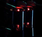
Sound like very nice bottles. Maybe I should try to score a few of these.
Sound like very nice bottles. Maybe I should try to score a few of these.
Per request, I set the power supply on 350 volts. I gould only get 25 watts after turning every knob there is to turn. There may be some power to be found by swapping OPT's.
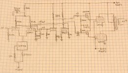
I have not drawn up a schematic for this mess yet. It is very similar to this one, I just used different tubes and changed some resistor values.
I decided to plug in a pair of 6BQ6GA's, the ones with 6AV5's inside. They laugh at this stuff, I started testing at 80 watts. Nothing glows, distortion is 4.4%. 90 watts, no glow, 7%. 100 watts, no glow, some clipping, distortion 10.8%. 110 watts, pale glow on screen grid, plate dark, distortion 15%. 120 watts, screen grid complaining brightly, very clean square waves, plate still dark. No more drive left,end of the dial!
Attachments
Thanks George, that helps a great deal. So it is the Defibrillator style B+ that makes this tube get up and sing. Still 25W would be all I would need for my woofer amp.
I noticed that the circuit uses LTP PI as first stage with balanced VAS after. Do you prefer the sound of this arrangement to the conventional one with PI just before the drivers? What are the practical advantages?
Sorry for the 20K questions. 🙂
hmm... just noticed there is no load resistor on the source followers. Does the output tube screen grid act as the load all by itself?
smoking-amp said:TAnd useless, unless someone needs up to 130 amps at 6.3 volts. It oughta power up some barrel sized TV station xmitter tube I guess. Its got big buss bars coming out the back.
Don
Voltage doubler... and use it as a car battery charger/jump-starter? 😀
Heck, if you were a bit closer (I've unfortunately not made it out of the state here, in a while, due to work), I'd be tempted to snag it from you and do exactly that (voltage doubler), to make a butt-kicking power supply, to test out a bunch of random car audio amps I have left over, from when I used to do that kind of stuff for a living a decade-and-a-half ago. I actually still have a bunch of 16v rated 21000uf caps, I think...
Regards,
Gordon.
tubelab.com said:Per request, I set the power supply on 350 volts. I gould only get 25 watts after turning every knob there is to turn. There may be some power to be found by swapping OPT's.
For 6CB5A, math shows that at Va = 350, Vg2 = 150, Rl = 2.5K, power should be around 65W, and I'm sure you could get more if you crank Vg2 up, but I've got no curves for that. What impedance OPT are you using?
After all the testing and the smoke clears how do some of these types sound for audio use?
I still seem to have a tough time understanding exactly why the tube manufacturers ended up with so many different numbers which use either identical guts in a different package or exactly the same tube overall with no real differences at all. Was this a scheme to make more money? It just seems that having to catalog and stock a lot of different numbers would have been more trouble than it was worth...
Very interesting stuff however for someone who was not there in the good old days of television, audio and tube electronics in general.
Speaking of OPT impedance, how do you go about choosing a load in screen drive? It doesn't seem that the data sheets are of much help here. I assume that Rp will be much different than in pentode mode use in deflection amp service so even using a rule of thumb would be a little tricky no?
No infrasound oscillations?
None whatsoever. I have seen some random HF oscillations with some tubes just as the amp goes into clipping. This is to be expected with the mess of clip leads and lack of stopper resistors on the output tubes.
Notes on the driver circuit:
The posted schematic is from the 6AV5 screen drive test I did over a year ago. It no longer exists. I started with this schematic and built the tag board driver used in these experiments. I used octal tubes (6SN7's) since I had some octal tag boards on hand. This circuit follows the original schematic pretty good, but several resistor values have been changed. I will be tweaking on this driver to improve the design as I use it. Once I have it where I like it I will draw up a schematic and post it.
hmm... just noticed there is no load resistor on the source followers. Does the output tube screen grid act as the load all by itself?
The original 6AV5 design did not have any load resistors. This one currently has 10K resistors returned to a - 25 volt power supply. I would prefer a higher negative voltage, but I don't have one handy.
I had noticed an odd distortion profile (see post #105) where the distortion peaks and then goes back down. It is the same regardless of the output tube being tested. I am now convinced that this is coming from the mosfet driver. It distorts as the current through the mosfets drops to zero. Further work is needed here.
I noticed that the circuit uses LTP PI as first stage with balanced VAS after. Do you prefer the sound of this arrangement to the conventional one with PI just before the drivers? What are the practical advantages?
About 10 years ago Kevin Kennedy (kevinkr) designed and published a P-P 300B amp. It used this driver topology. I built a modified (OK, hacked) version of this amp. it is the only one of my old amps that I still have. It sounds great. I have preferred this topology ever since, but it does require more tubes. Exact tube section matching is not required, but some tubes are so imbalanced that they can't be used.
Practical advantages? The usual split load PI requires an equal load on each output to work right. The common practice it to tie the output of the PI directly to the grids of the output tubes, and this does well in typical static bench testing. However real music is anything but static, and the input impedance to the output tubes under high signal conditions is anything but constant and equal. Driving the screen grid is far worse. I prefer a buffer between the PI and the output tube. I have built amps with the usual split load PI followed by a buffer stage. It works well, but screen drive requires some extreme drive voltage. This means that all of the circuitry must be optimized for gain and dynamic range. This topology has done the best for me in that regard.
I actually still have a bunch of 16v rated 21000uf caps, I think...
Due to the large population base of thumpa thumpa car owners in south Florida, you can buy a 1 Farad 16 volt electrolytic cap at Wal Mart here. You can also get some serious speaker wire at Wal Mart for reasonable money. That is what I am using in my systems.
For 6CB5A, math shows that at Va = 350, Vg2 = 150, Rl = 2.5K, power should be around 65W, and I'm sure you could get more if you crank Vg2 up, but I've got no curves for that. What impedance OPT are you using?
Since I was writing about the 6BQ6's at the time of mashaffer's request, I assumed that was the tube he was talking about. My 350 volt test was run with 6BQ6's and a 6600 ohm load. 25 watts is about what you would expect. Power did not go up when the load was configured to 3300 ohms. I think the cathode current is limited under these conditions.
So it is the Defibrillator style B+ that makes this tube get up and sing.
All of these experiments are using SCREEN DRIVE. This is a relatively unexplored territory, so most of are learning as we go along (myself included). In a screen driven application the screen being driven positive is what casues the plate voltage to decrease. Any pentode does not like the screen grid operating at a voltage significantly above the plate voltage. The screen grid will hog all of the current, and get very hot (visible glow). Brief excursions on signal peaks are OK.
Lowering the plate voltage also lowers the screen drive voltage in my design since they are both operating on the same power supply. Two supplies could be used, but that would risk blowing the screen grid right out of the tube!
The amplifier output impedance is higher than a similar tube in normal triode operation. It is similar to the same tube used in pentode mode. NFB will likely be required.
After all the testing and the smoke clears how do some of these types sound for audio use?
I have done no listening tests on the recent amplifiers. The original 6AV5 screen drive experiment amp did sound pretty good, but made the lack of feedback obvious in the bass department.
Speaking of OPT impedance, how do you go about choosing a load in screen drive?
I have been using the "guess and try it, adjust as necessary" method for now. I have home made load bank that I usually use which goes in .1 ohm steps from 1 ohm to 11 ohms, but I can't use it here since these amps put out enough power to blow it in half.
I will be doing a lot more screen drive experiments in the next few months. Recent surgery had me confined to the house for a week, so I had ample time to blow stuff up. I am back at work now, so the experimenting will slow down.
GW:
"Voltage doubler... and use it as a car battery charger/jump-starter? "
Well, I've got another one on the way, (hopefully still WITH the serial port option card this time!) so two in series would do the trick easily. I'm wondering now what voltage one needs to recharge a Hybrid vehicle battery set. Probably needs high voltage for a big series battery set.
For impressive 12V power, check out the Kepco RCW 12-125K or RAX 12-125K. 1500W 125 Amp. I got one on EBAY a year ago cheap, like $50.
There are actually a bunch of Sorensen, Lambda, Kepco, Power-One ... and umteen other makes that have similar models. Usually its the smaller, more practical models that get bid up. I've seen some 6KW and 10 KW monsters go for a song because no one wants to pay for the shipping on them.
M:
"how do you go about choosing a load in screen drive? It doesn't seem that the data sheets are of much help here. "
Some of the tube data sheet sets have a curve set for g1 = 0V and g2 being swept up from 50V to 200V or so. Just think of g2 as the new control grid. Same procedure as usual. The 6CB5A sheets have this on page 4 (Sylvania):
http://frank.pocnet.net/sheets/137/6/6CB5.pdf
The plate resistance in g2 drive mode should be similar to the usual pentode mode, so some local or global feedback to control it will typically be needed.
"After all the testing and the smoke clears how do some of these types sound for audio use? "
The trick here will be, I think, to use some local feedback back to the driver stage to get the output Z down, and this will largely transfer the "sound" to the character of the driver tube(s). Tubes operating with g2 drive tend to be fairly linear of themselves, if the drive is low Z. Lots of possibilities for clever designs here. The main difficulty of course is to get high enough voltage swing out of the driver and sufficient current drive to handle the g2 current draw. Mosfet followers are key for that. Using beefy driver tubes that can handle full B+ is another key (or use the center tapped inductor load idea recently posted).
Don
I'm wondering now what voltage one needs to recharge a Hybrid vehicle battery set.
The 2001 to 2003 Prius used a 273.6 volt battery pack. The newer ones use a 201.6 volt pack. The pack has an internal controller that makes it hard to charge without communication over the CAN bus. There are three internal relays that must be closed before the battery terminals are available to the outside world.
- Status
- Not open for further replies.
- Home
- Amplifiers
- Tubes / Valves
- Tube sale at AES