I got my little box of joy today from AES. The 6CB5As are interesting - they look a lot like the steroid-enhanced 6BG6GAs touted as 7027A equivalents, except the plates are blackened a little more. They are made by Sylvania, just like the 6BG6s, and are fairly recent manufacture, as the base sports a zip code... I'm looking forward to giving a pair of these a beating in my "Miz Piggy" 6CD6GA SE screen-driven amp when I get its/her guts sorted out. I have GE 6CD6GAs, GE and Westinghouse 6DQ5, and these 6CB5As. They all have plate structures of approximately the same size. The screen ratings are irrelevant (screen drive). Which one will be the best performer?
I also got a quad of the "unbreakable" Chinese 6L6GCs. They look plain and unassuming, but reasonably well-made. I will face them off against some recent manufacture Svetlanas when I figure out a project where I can slot them.
Also in the box - 6JK8s and 6JE8s for side projects (as if I needed any more). It would be interesting to do a classic cheapo push-pull using the 6JE8 or 6AW8A for front-end duty rather than the usual tired 6U8 or 6BL7. I'm nagging a colleague at work into refurbishing a nice old Scott 399 receiver, which uses a 6BL7 for front end and phase-splitter duty. They really starve the imput stage for both voltage and current. It's time to change that and see if it makes a listenable difference, even if I have to make my own amp to check out the concept..
I got my goodies box as well. It was quietly waiting for me in the front door.
My 6CB5A's have dark plate and carry the National Electronic Brand, not sure they were made by Sylvania or not. I also ordered half a dozen EC91 and will look at MJ's book to see how I can use them 🙂 I have the gut feeling that I will have another before this sale ends .......
My 6CB5A's have dark plate and carry the National Electronic Brand, not sure they were made by Sylvania or not. I also ordered half a dozen EC91 and will look at MJ's book to see how I can use them 🙂 I have the gut feeling that I will have another before this sale ends .......
No need to see that many. Long ago I was taught that GT meant glass-tiny. This was the designation for the small envelope with an octal base. The GA designation was for the larger size. and G was the curved version. When you went to buy tube boxes you ordered size by these letters. 7 and 9 pin tubes were known as miniatures.
This is indeed what is spelled out in the tube manuals that I have, and is the accepted norm. I am sure that most of us have found exceptions to this though. I have plenty, especially the distinction between G and GA. So far the GT - GA distinction holds up fairly well.
I am sure that as soon as I say that all 6BQ6GA's are "fat boys" I (or someone else) will find an exception. I have several 6DQ6GT's. They are all fat. I have a long history with the 6BQ6 and 6DQ6 tubes. They were what I tubes learned on, since they were readilly available in the trash. I remembered the fat 6BQ6's from my early days. I could make the most wicked sounding guitar amps with them. I haven't seen any of them in 40 years until this week.
My AES goodie box should arrive today. I already have a new shopping list.
I also got a quad of the "unbreakable" Chinese 6L6GCs.
I still have my first pair (and a few more). They were used (in a Bandmaster) when I got them. They have been seen glowing brightly several times, and just keep on working. They are not the best sounding for HiFi, but not bad. I got some more on Ebay for $3 each.
OK, the box showed up. The 6AQ4's turned out to be Mullard EV91's. There was only one 6DG6, the rest were actually 6W6's, some quite old. They sent one 6W4 by mistake, OOPS. I set these all aside and went straight for the big boys.
The 6CB5's were many different brands, mostly GE. They seem to all be made by RCA or Sylvania, except for one odd ball. It is marked Westinghouse, looks like Sylvania guts, has a stop sign type number and the grid radiators are different than all others.
They are easy to identify, the Sylvania's have large rectangular black plates with no holes in them. There are heat radiators on the top on G1 and G2. The type number is printed on the side with U.S.A. underneath. The RCA's have grey rectangular plates, slightly smaller than the Sylvanias, with three rectangular holes in each end. They have the familiar RCA stop sign type number. I got two RCA branded tubes that are made by Sylvania. The GE's are mostly by Sylvania, but a few are RCA. The Zenith, Raytheon, Dumont, and Sylvania tubes are made by Sylvania.
I made an adapter to test these in a Simple SE. First I tried UL mode. With no signal input the B+ can be cranked to 400 volts without grid glow. Plate glow starts to show at about 30 watts on both types. As you increase the signal the plate cools off, while the screen starts to glow. UL may work, but at a lower voltage.
Next, I decided to try SE pentode mode. Here I could run the screen and the plate on seperate power supplies. I wound up with the plate supply maxed at 550 volts. I played the screen grid and control grid knobs against each other to find maximum power at minimum distortion, while avoiding meltdown.
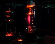
It is easy to get 20 to 25 watts output at 5% distortion, at several settings, but I wanted more. I found settings that provide 35 WATTS RMS at 8% distortion from a single $2 tube. Plate voltage is 550 volts. Screen grid voltage is 260 volts, and cathode current is 130 mA. This is 72 watts input to the tube and 35 watts out for a tube dissipation of 37 watts. As seen below, there is no visible glow with the room lights on.
The Sylvania is on the left, the RCA on the right. Only the RCA has plate voltage applied.
The 6CB5's were many different brands, mostly GE. They seem to all be made by RCA or Sylvania, except for one odd ball. It is marked Westinghouse, looks like Sylvania guts, has a stop sign type number and the grid radiators are different than all others.
They are easy to identify, the Sylvania's have large rectangular black plates with no holes in them. There are heat radiators on the top on G1 and G2. The type number is printed on the side with U.S.A. underneath. The RCA's have grey rectangular plates, slightly smaller than the Sylvanias, with three rectangular holes in each end. They have the familiar RCA stop sign type number. I got two RCA branded tubes that are made by Sylvania. The GE's are mostly by Sylvania, but a few are RCA. The Zenith, Raytheon, Dumont, and Sylvania tubes are made by Sylvania.
I made an adapter to test these in a Simple SE. First I tried UL mode. With no signal input the B+ can be cranked to 400 volts without grid glow. Plate glow starts to show at about 30 watts on both types. As you increase the signal the plate cools off, while the screen starts to glow. UL may work, but at a lower voltage.
Next, I decided to try SE pentode mode. Here I could run the screen and the plate on seperate power supplies. I wound up with the plate supply maxed at 550 volts. I played the screen grid and control grid knobs against each other to find maximum power at minimum distortion, while avoiding meltdown.
It is easy to get 20 to 25 watts output at 5% distortion, at several settings, but I wanted more. I found settings that provide 35 WATTS RMS at 8% distortion from a single $2 tube. Plate voltage is 550 volts. Screen grid voltage is 260 volts, and cathode current is 130 mA. This is 72 watts input to the tube and 35 watts out for a tube dissipation of 37 watts. As seen below, there is no visible glow with the room lights on.
The Sylvania is on the left, the RCA on the right. Only the RCA has plate voltage applied.
Attachments
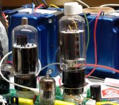
My 6CB5As are an equimolar mix of National and Sylvania, both looking pretty much alike except for the logos. Testing will be at 400 Vp with whatever plate current feels right for the 125ESE output transformers.
Wrenchone:
"The 6CB5As are interesting - they look a lot like the steroid-enhanced 6BG6GAs touted as 7027A equivalents, except the plates are blackened a little more."
Tubelab:
"With no signal input the B+ can be cranked to 400 volts without grid glow. Plate glow starts to show at about 30 watts on both types."
I'm wondering if the special 6BG6GAs are close to red plating then at 30 Watts or 35W (7027A). The plates in a real 6L6GC look a little small to me for their 30 Watt rating compared to the plates in a typical 30 Watt Horizontal Output tube. In fact, some of the 18 Watt Horiz. Output tubes have bigger plates than the 6L6GC.
Don
My observation, too. Tht's why I'm continuing with the 6CD6GA, despite its 20W paper dissipation rating.
GU50 has almost the same size like 6L6, but it dissipates much more power though is not black, And once it is red, it continue working without any sequences. The matherial matters as well as degree of blackness and area of the radiating surface.
Wb:
"The matherial matters as well as degree of blackness and area of the radiating surface."
Maybe the glass material can take higher temps on some tubes (Pyrex or equiv. maybe). Any data on the GU50 glass temp spec? But if thats the main difference, then providing some forced air ventilation around the tube socket should allow much higher diss. ratings. (The amateur radio guys used to operate some tubes in oil baths) Also some tubes have plate radiators attached to the G1 or G2 top grid end, but again usually its the Horiz. Output tubes that have these. Also, the G plate radiators are not very consistently present across various brands of the same tube type.
Don
Prt of the secret as well may be controlling the electron trajectories in the tube so that the heat is more evenly distributed across the anode surface.
wrenchone said:Prt of the secret as well may be controlling the electron trajectories in the tube so that the heat is more evenly distributed across the anode surface.
May be. GU50 was initially designed by Telefunken.
GU50 has almost the same size like 6L6, but it dissipates much more power though is not black, And once it is red, it continue working without any sequences.
The typical receiving tube has plates made out of steel, or a similar alloy. They are coated to enhance their thermal radiating properties. The primary design criteria is cost. Grid material is often a similar alloy. As the operating temperature rises these materials will "outgas" impurities that contaminate the vacuum. Many of these impurities will ionize under less than atmospheric pressure (partial vacuum) leading to a bluish glow. Continued operation at a high temperature will lead to a shorter tube life due to vacuum contamination.
Sweep tubes have a tough life. In the 50's and 60's the average household had one, maybe two TV's. Houses weren't air conditioned, and the TV was on for several hours every day. The sweep tubes always run at full power, you can't "turn the volume down" on the sweep, or the picture on the TV will shrink. To give the typical sweep tube any chance of living a normal life, the plates were oversized for their rated dissipation. The cathodes were usually oversized as well for extra emission capability as they got older.
Look at the ratings for tubes that are specified for both audio and sweep use. The plate dissipation is typically 20% or more lower in sweep tube service. An example already mentioned is the 6W6. It is rated for 10 watts as a class A amplifier, and 7 watts as avertical output tube. Same for the 6V6, 12 watts, goes to 9 watts.
Applying this in reverse allows us to hammer the sweep tubes a bit harder than their published ratings. As tube manufacture started to decline and assembly lines were shut down, some manufacturers started stuffing the envelopes with some unusual combinations. Why make several different plate structures, just put the biggest ones into all of the tubes that it will fit. This is why we have 6BQ6's with 6FW5 plates in them. These can take far more then their published 11 watts. I have found exactly the same plate structure in several different sweep tubes.
In the very last years of tube manufacture, some suppliers (especially Sylvania) got real creative with what they stuffed in the glass. This is why we have 6GB6's with 7027 guts, and 6B4's with 6AV5 guts (yeah that is a sweep pentode stuffed into the glass of a DHT).
Transmitting and industrial tubes were made to a different design criteria. Reliability was the prine design criteria. The plates often contained rare elements that would absorb stray ions when heated (tantalum was used in the 833A). Operating the plate with a red glow is actually required in some of these tubes. The grid wires were often plated with inert metals (gold). I don't know much about the GU50, so I can't speak for its design.
The 6CB5's that we have were all made during the prime days of the vacuum tube era. It looks like there is one basic design with two manufacturers. They seem pretty typical of late 50's early 60's sweep tubes (like the 6CD6). They are specced at 22 to 24 watts depending on whose data that you read. There is some extra room in those ratings that is typical of sweep tubes, but there doesn't appear to be any "super versions" out there. These were used in the first 21 inch color TV's that had a 70 degree deflection angle. It is one of the biggest sweep tubes of that era.
Tube TV died out when the biggest TV's were 25 inch with a 90 degree deflection angle. This required more power from the sweep tubes. The 6JE6 was designed for this size TV. They were just barely enough, and died often. That is why we have 6JE6A, B, and C, and the 6LQ6. later the 6LF6 and the 6LW6 were designed. These are the biggest and baddest of the TV sweep tubes. They were constantly improved, and some of the last ones don't red plate at 90 watts, even though they have a 40 watt rating!
OK, I thought that getting 25 cents per watt from the 6BQ6GTB's in SE was cool. I just trashed the watts per tube dollar threshold. I am now at a nickel per watt, without anything glowing! How?
Well, I didn't buy a bunch of 6CB5's for nothing. Today I wired up a screen drive amp and turned it up, and up, and up. With my power supply maxed, and its current meter pegged hard, the power meter is reading 120 watts! Dialing the drive back until the distortion comes down to 5%, the watt meter reads 85 watts, so I will call this an 80 watt amp. At $2 per tube, $4 for the pair, this is $.05 per watt. I doubt that this can be bettered, unless I can find a bigger power supply.
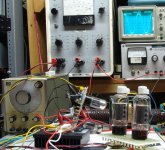
This photo shows the tag board and clip lead design. The amp had been quietly cranking along at 90 watts when this picture was taken.
The tubes are biased near class B. The idle current is 15 mA per tube. This is achieved with a plate voltage of 550 volts. The control grid is at -11 volts, and the screen grid idles at +35 volts.
Well, I didn't buy a bunch of 6CB5's for nothing. Today I wired up a screen drive amp and turned it up, and up, and up. With my power supply maxed, and its current meter pegged hard, the power meter is reading 120 watts! Dialing the drive back until the distortion comes down to 5%, the watt meter reads 85 watts, so I will call this an 80 watt amp. At $2 per tube, $4 for the pair, this is $.05 per watt. I doubt that this can be bettered, unless I can find a bigger power supply.
This photo shows the tag board and clip lead design. The amp had been quietly cranking along at 90 watts when this picture was taken.
The tubes are biased near class B. The idle current is 15 mA per tube. This is achieved with a plate voltage of 550 volts. The control grid is at -11 volts, and the screen grid idles at +35 volts.
Attachments
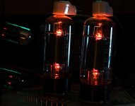
Here is my usual photo with the lights out. The amp is operating at 80 watts. Notice what is missing from the photo. There is no glow. Careful observation in a totally dark room with a magnifying glass reveals that the screen grids start to barely glow at power levels above 100 watts, and are readilly visible at 120 watts.
This proves that it is possible to violate the screen grid ratings in screen drive mode. This will not be a problem in normal use since this power level should be seen only on extreme signal peaks, and the amp is clipping heavilly.
Call this an 80 watt amp with 40 watts of head room!
This proves that it is possible to violate the screen grid ratings in screen drive mode. This will not be a problem in normal use since this power level should be seen only on extreme signal peaks, and the amp is clipping heavilly.
Call this an 80 watt amp with 40 watts of head room!
Attachments
Hi George
Due to you I am already on my second AES box, this time including 20 pieces of the 6CB5 (but I still missed to buy some 12AV5GA and 6Y6G, for the cool bottle).
Can you give some more details about the driver stage for the 6CB5 output stage? Is it similar (the same) as the driver stage you used for the 6AV5 screen driven experiment? How much VRMS are needed for the 6CB5 grids?
Surely you can get more power with a higher B+, I think you are probably clipping the output stage now. If I am not mistaken SY is using about 700V in his 6LW6/6LF6 design.
Keep on the good work, but also take care that you can do that for a lot of years to come!
Erik
Yeehaw! Maybe your push-pull pcb design in the works can be a screen driven affair using cheap sweep tubes. I want to try a screen drive push-pull, but not untill I clear my bench of the umpteen projects stacked ahead of it. I bought a bunch of 17JN6s form AES with the intention of kicking them around. Husky plates on those little critters...
As for your current Frankenstein bench monster, I'd love to know the peak drive voltage in hard clipping - those poor hard-pressed screens might have been above plate potential, and acting as surrogate anodes.
As for your current Frankenstein bench monster, I'd love to know the peak drive voltage in hard clipping - those poor hard-pressed screens might have been above plate potential, and acting as surrogate anodes.
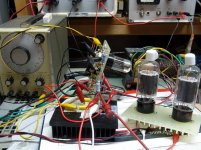
Here is a close up picture of the amp. There are 3 main modules.
The tag board standing on its side in the rear is the driver board. It uses 2 6SN7's. The first is an LTP phase splitter. The second is a differential amp. DC coupling is not used in order to maximize the available output voltage swing.
The heat sink inhabited by sand state life forms is the mosfet follower. It contains two ST micro 900 volt 3 amp mosfets. These can feed the screen grids with enough current to make them glow.
The tag board in the foreground contains the two 6CB5's and nothing else. All connections except for the filament and plate are made with clip leads.
The OPT is seen behind the left output tube. It is an "80 watt" 6600 ohm guitar amp OPT that I got on Ebay several years ago. It will saturate badly at these power levels below 100Hz.
The large brown object behind the OPT is a 500 watt load resistor. Yes, is is not a purely resistive load, but it is the only thing that I have that will handle this kind of power. I learned from experience a few years ago that the OPT will instantly catch fire if the load goes open at this power and B+ voltage.
Pray for the people in southern Louisiana. Tonight and tomorrow will be very ugly. The hurricane is already being blamed for 2 deaths, HERE in south Florida. Two tourists drowned in the unusually high surf.
Attachments
Maybe your push-pull pcb design in the works can be a screen driven affair using cheap sweep tubes.
I am working on a PCB that can be used for high output screen drive, and conventional control grid use too. Unfortunately the two requirements are somewhat conflicting. That is the real reasons for these screen drive experiments.
Surely you can get more power with a higher B+, I think you are probably clipping the output stage now.
The output stage is definitely running out of headroom, but the driver may be also. My big power supply only goes to 550 volts, and my 1KV supply current limits at 200 mA. So for now, I am power supply limited.
Can you give some more details about the driver stage for the 6CB5 output stage? Is it similar (the same) as the driver stage you used for the 6AV5 screen driven experiment?
It is basically the same. I used different tubes and resistor values, but the circuit is the same. I will draw up a schematic, and make a PCB once I have it working the way that I want.
As for your current Frankenstein bench monster, I'd love to know the peak drive voltage in hard clipping - those poor hard-pressed screens might have been above plate potential, and acting as surrogate anodes. ..... How much VRMS are needed for the 6CB5 grids?
OK, it is 7 PM here, and the storms have subsided for now. I am going outside to grill some food. I will make some more measurements later tonight.
tubelab.com said:
I don't know much about the GU50, so I can't speak for its design.
Nickel alloy anode.
- Status
- Not open for further replies.
- Home
- Amplifiers
- Tubes / Valves
- Tube sale at AES