Thanks for the explanation!
Is that because the screen grids are at a positive potential, while in a conventional stage they are at a negative potential? This brings me back to a question I am carrying with myself for quite some time now... in the screen driven amps by Berning the control grid (number 1) is grounded while the screen grid is kept slightly negative. SY also posted that his screen driven amp is working this way. In your designs, however, you have the control grid at a slightly negative voltage, while the screen grid is (slightly) positive. Apparently both ways work, and I wanted to try both ways out, but never came to it... yet.
What I was thinking (and that thinking process is going for a long while now) is that a 'universal' driver stage (for both screen driven as well as conventional drive) could be made much easier if the screen driven version would be driven in the 'berning' fashion (negative screens) as this would be the same as a conventional stage. Besides that there would be no need for biasing of the control grids either, as they can just be grounded.
Erik
I am working on a PCB that can be used for high output screen drive, and conventional control grid use too. Unfortunately the two requirements are somewhat conflicting. That is the real reasons for these screen drive experiments. quote:
Is that because the screen grids are at a positive potential, while in a conventional stage they are at a negative potential? This brings me back to a question I am carrying with myself for quite some time now... in the screen driven amps by Berning the control grid (number 1) is grounded while the screen grid is kept slightly negative. SY also posted that his screen driven amp is working this way. In your designs, however, you have the control grid at a slightly negative voltage, while the screen grid is (slightly) positive. Apparently both ways work, and I wanted to try both ways out, but never came to it... yet.
What I was thinking (and that thinking process is going for a long while now) is that a 'universal' driver stage (for both screen driven as well as conventional drive) could be made much easier if the screen driven version would be driven in the 'berning' fashion (negative screens) as this would be the same as a conventional stage. Besides that there would be no need for biasing of the control grids either, as they can just be grounded.
Erik
What I was thinking (and that thinking process is going for a long while now) is that a 'universal' driver stage (for both screen driven as well as conventional drive) could be made much easier if the screen driven version would be driven in the 'berning' fashion (negative screens) as this would be the same as a conventional stage. Besides that there would be no need for biasing of the control grids either, as they can just be grounded.
The amp that is on my bench has knobs for plate, screen, and control grid voltage. I arrived at the current set of operating conditions by "twisting the knobs" for an hour or so to minimize distortion over all audio power levels. It has been my (limited) experience that a slightly negative control grid with a corresponding increase in screen grid voltage lowers crossover distortion for a given idle current. This may be different with a different tube.
I have not studied Berning's amplifiers. It is possible to operate some tubes with the control grid grounded. This may, or may not lead to the screen grid operating at a negative voltage AT IDLE, depending upon the plate voltage. I assure you that the screen grid must be driven highly positive under signal conditions and in doing so it will draw current. The positive excursion may be a few hundred volts, and the driver must be capable of delivering this voltage, at considerable current without distortion. These requirements are not unlike driving the control grid of say an 845 or 833A. The control grid of most receiving tubes does not need anywhere near this much voltage, and does not draw much current.
So we need a driver that can put out several hundred volts peak to peak, pump out some current, and have an adjustable DC offset that can go from way negative to way positve. I have been there done that, it is called PowerDrive. The trick is the tube stages feeding the mosfet.
Many tube purists (myself included) believe that any amplifier design should have as few capacitors in the signal path as possible. It is possible to directly couple the first tube to the second tube in the design of many driver circuits. However this requires the second tube to operate with its cathode 100 or more volts above ground. This uses up at least 100 volts of output swing.
So the real differences in the driver requirements is the peak to peak drive voltage requirements. Now you know why I have assembled a monster pile of sweep tubes. I need to find out just what these requirements are before I can figure out how to feed them.
Now, the amp is hot and I have some measurements to make.
Thanks for the extensive explanation! You are absolutely right that the voltage is only negative at idle, when the tube is cut off (class B, after all). In the Berning amps the screens go well in the positive regime to allow current to flow through the output tubes. Berning uses 6SN7 CF's, but surely the power drive does the job way better (SY also uses mosfet's in his design) as it allows less output impedance and swinging closer to the B+ (in comparison to a CF tube).
There is another recent thread on the use of a CT plate choke as load for an LTP stage, allowing one to generate double the swing than would be possible from a resistor loaded LTP. Some people commented that they used the primary of an 8k output transformer for the job, but I was thinking how well a US$13,00 interstage from EDCOR would do it (thinking about the 10k:10k, with primary and seconday in series, B+ going to the 'new' CT and the 'extremes' to the plates of the driver tubes). This would only generate swing, but that is all that is needed anyway at this stage, as the current amplification is done by the power drive.
Do not take this to serious, it is mostly loud spoken brainstorming.
Erik
There is another recent thread on the use of a CT plate choke as load for an LTP stage, allowing one to generate double the swing than would be possible from a resistor loaded LTP....Do not take this to serious, it is mostly loud spoken brainstorming.
Serious, serious enough to buy some chokes and P-P OPT's. It is an option, and one I will explore. I have some chokes and OPT's to experiment with. There are almost as many people who dislike iron as there are those who dislike caps. I would like to find an iron free solution with only one coupling cap.
I'd love to know the peak drive voltage in hard clipping - those poor hard-pressed screens might have been above plate potential, and acting as surrogate anodes.
BINGO! At the moment that the screens are reaching for the sky, the plates are touching the ground, literally.
I did some measurements as promised. First off, I noticed some irritability in my tired power supply, so I put a 100uF motor run cap across the output. I was rewarded with 10 more watts when driven to clipping.
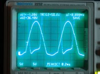
I put one scope probe on the screen grid, and the other on the plate, and took some pictures. This one is with the amp cranked to 130 watts. The scale is 50 volts per division, and zero is the second division from the bottom. The screen drive voltage goes from about -15 volts to +250 volts. The plate voltage touches zero and settles to about +35 before heading to some extreme positive voltage above 1KV.
There are two observations here. There is limited negative screen voltage. This is again a limitation of my power supplies. The bias outputs on the typical vacuum tube power supply can only source 1 or 2 mA. The idle current on the mosfet is about 10 mA, so I am using a SS power supply that only goes to 25 volts. In the final design, I believe that the negative screen excursions should be limited. Screen grids were never meant to be at -250 volts, and once the tube is cut off, why go further.
There is a small glitch seen in the plate and screen voltages as the amp comes out of clipping. This is an oscillation that only happens when the amp clips. Too many clip leads. The oscillation moves around as the clip leads are moved. Under some conditions it wipes out the nearby TV set and makes the computer speakers hiss!
Attachments
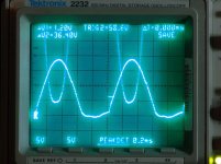
Next picture. I turned down the drive until the amp puts out 80 watts. The screen grid is still being violated. The plate swings down to 40 volts while the screen goes up to 180 volts. The two traces touch at 50 watts.
I noticed an unusual distortion VS power output curve, 6.6K ohm load, zero feedback:
Power Distortion.
1 watt 2.0%
5 watts 3.1%
10 watts 4.1%
20 watts 5%
50 watts 4.4%
70 watts 2.4%
80 watts 4%
90 watts 6.8%
100 watts 10.4%
110 watts 15.4%
120 watts 21%
130 watts 26%
I noticed an unusual distortion VS power output curve, 6.6K ohm load, zero feedback:
Power Distortion.
1 watt 2.0%
5 watts 3.1%
10 watts 4.1%
20 watts 5%
50 watts 4.4%
70 watts 2.4%
80 watts 4%
90 watts 6.8%
100 watts 10.4%
110 watts 15.4%
120 watts 21%
130 watts 26%
Attachments
OK, time for one more expeiment, and this one moved the cost per tube watt. I connected my 8 ohm load to the 16 ohm tap. This reflects a 3.3 K ohm load to the tubes. What happened. Well now I get 115 watts at 5% distortion, and 154 watts at 10%. Turning the drive up any further sends my power supply into convulsions. The current must be over 500 mA. I had to shut the power supply off and let it cool.
This load now causes plate glow to appear before screen grid glow. Clearly, there is a happy medium out there somewhere. More experiments tomorrow if the weather is still bad.
This load now causes plate glow to appear before screen grid glow. Clearly, there is a happy medium out there somewhere. More experiments tomorrow if the weather is still bad.
Tubelab:
"The two traces touch at 50 watts.
I noticed an unusual distortion VS power output curve, 6.6K ohm load, zero feedback: ..."
Likely the increase in screen current at plate V / screen V crossover is nulling out the expansive 3/2 power law pentode plate current curve till 80 Watts or so.
"The two traces touch at 50 watts.
I noticed an unusual distortion VS power output curve, 6.6K ohm load, zero feedback: ..."
Likely the increase in screen current at plate V / screen V crossover is nulling out the expansive 3/2 power law pentode plate current curve till 80 Watts or so.
I got this dumb idea that I could tie G1 to G2 and feed them both at the same time. It sounded like a reasonable idea, but resulted in an instantly exploded mosfet. The mosfet looks like it got hit by lightning, and the only path for current to flow is into the tube, unless I connected something up wrong.
Attachments
tubelab.com said:OK, time for one more expeiment, and this one moved the cost per tube watt. I connected my 8 ohm load to the 16 ohm tap. This reflects a 3.3 K ohm load to the tubes. What happened. Well now I get 115 watts at 5% distortion, and 154 watts at 10%. Turning the drive up any further sends my power supply into convulsions. The current must be over 500 mA. I had to shut the power supply off and let it cool.
This load now causes plate glow to appear before screen grid glow. Clearly, there is a happy medium out there somewhere. More experiments tomorrow if the weather is still bad.
George- one suggestion:
Maybe, you might want to try and find a toroidal transformer (repurposed power transformer even?) that could give you about a 4.5K load to the plates...
With screen drive, the bias is so low, that even IF you had offset (different bias current on one output tube vs. the other), the magnitude of the bias difference would still be TINY, compared to nomal G1 drive mode. A 50% offset would only be a couple of milliamps, instead of tens of milliamps! I'm willing to make a SWAG that this could obviate the problem of easy DC saturation normally seen in output toroidals...
Plus, there's absolutely MASSIVE toroids out there... reaonsbly cheap... Antek, among others...
I'd just like to see if this would work. Had the idea a while back, and just haven't had ANY time to even get the bench cleared off enough to even hook up a circuit...
Regards,
Gordon.

Looks like both tube sales just ended today, Sept 1st.
Bummer, I already have a new list, and more 6CB5's were at the top.
Maybe, you might want to try and find a toroidal transformer (repurposed power transformer even?) that could give you about a 4.5K load to the plates...
My guess would be closer to 4K. I have two monster Plitron toroidal OPT's that I bought surplus. I have been itching to use them. They are rated for 400 Watts at 20Hz, 1250 ohms CT. This is looking like 6 X 6CB5's per channel. I am going to need a lot more power supply. Fortunately I already have a big Antek 400 - 400 volt 400 VA toroid. It should be enough for one channel.
and just haven't had ANY time to even get the bench cleared off enough to even hook up a circuit...
This experiment is sitting on top of a 1KV power supply that I got from Ebay. I am going to need the whole bench to build that big guy. In reality it must wait for some other experiments to get done.
After I replaced both (well 1 1/2) mosfets, and connected everything back the way it was, the amp is live again. So, whats next? Someone mentioned a BF toroid.
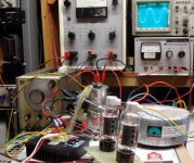
I hooked up the Plitron. I tried the 8 ohm load on all of the output taps and picked the one with the most power. I don't have the data sheet handy, but I think that it is on the 4 ohm tap giving a 2500 ohm load. The amp behaves about the same as before, except that I can make 130 watts at 40 Hz with 5% distortion. Some saturation is seen at 20 Hz, especially above 100 watts. There has been no attempt to balance anything, or match tubes.
The picture shows the size of this monster. The scope trace is at 1KHz and 150 watts. Distortion at this level is 7%. There is a pale glow of the plate in a dark room, screens are dark.
Attachments
"So, whats next? "
6CD6/6EX6 and 6DQ5 have very similar specs to the 6CB5A if on hand. Pinouts are compatible with the 6CB5A with a little finesse.
6HJ5 looks like nearly the same tube in a 12 pin base. All have g2/g1 Mu around 3.3 to 4.2 and watts diss. around 22 to 24.
Probably a bunch of other Horiz. Output tubes too, but these are cheap ones.
Don
Horizontal sweep tubes in the 30W region tend to get sucked up into the RF linear amp vortex. I'm mostly concentrating on the 6CD6GA, the 6DQ5, the 6HF5, and now, the 6CB5. Since these will slotted onto a single ended class A amp, it doen't make a whole lot of sense driving them harder than 2X bias current. What goes up, must come down, and all that. I've run the GE 6CD6s at ~25W dissipation without undue consequences. I'm using about 400V B+ with Hammond 125ESE output iron, so I could push the bias current up to the 30W level without having to ratchet down from 5k impedance to 2.5k. I'll have to wait for a push-pull project to get anything close to the insane power George is eking out of his circuits.
How long is the plate in the 6HF5? 1 3/8 inches? Just curious, since it uses the same filament current as the 6HJ5 and has the same size bottle too (other than the plate cap on top).
I also would be curious to know the length of the plate in the "super" 6BG6GA tubes (and the regular one too) if anyone has one.
The 6KV6A/17KV6A has the same length plate, 1 3/8 inch I think (don't have them handy presently), as the 6HJ5, but is rated at 28 Watts like the 6HF5.
(the 6HJ5 sells for 1/4 the price though)
Don
I measured an RCA 6HF5, and its plate was about 1 3/8" - same for the Sylvania "super" 6BG5GA (I don't have any normal 6BG5s). Radiator fins are also about the same size. King of the tall plates - GE/Westinghouse 6HV5A and Russian EL509, both with 2" plates (for different reasons). The 6HV5A will take a different set of conditions to light its fire than the sweep tubes - I'll be working on that down the line. Moral of this thread - sweep tubes rock, it's just that some rock harder than others....
I have some old 6BG6GA's. Comparing to the super 6BG6GA,
- The Sylvania and the Dumont have same plate structure as the
with the exception that the super has the getter on the top, whereas
the normal's have the getter on the side. Plate color is grey.
- The old Tung Sol 6BG6GA has black plate color and has the getter
on the top. The plate is about 1 3/8" long, but it is smaller when
I compared them from the side, i.e the depth of the rectanguler
plate box is not as "thick".
pchw said:I have some old 6BG6GA's. Comparing to the super 6BG6GA,
- The Sylvania and the Dumont have same plate structure as the
with the exception that the super has the getter on the top, whereas
the normal's have the getter on the side. Plate color is grey.
- The old Tung Sol 6BG6GA has black plate color and has the getter
on the top. The plate is about 1 3/8" long, but it is smaller when
I compared them from the side, i.e the depth of the rectanguler
plate box is not as "thick".
Yeah, the old ones are 807's without the shielding and with an octal base.
Look familiar?
An externally hosted image should be here but it was not working when we last tested it.
"So, whats next? "
What's Next? Many times, including several times this weekend, I have run into limitations imposed by my collection of power supplies. I have considered designing a complex regulated supply capable of melting transmitting tubes at will, but it is obviously a complex undertaking, one that I am not ready to do yet. I have thought about building the mother of all SMPS's, but my initial experiments just make blown mosfets (I am still learning). So I think that I will just make a simple Variac - Industrial transformer set up to get by with for a while.
6CD6/6EX6 and 6DQ5 have very similar specs to the 6CB5A if on hand. Pinouts are compatible with the 6CB5A with a little finesse. 6HJ5 looks like nearly the same tube in a 12 pin base.
I have some of these tubes, and they are within reach of my current power supplies. I will probably test them in this P-P set up to see what happens. I obviously will pop in a pair of 6LW6's which are the grandaddy of all sweep tubes. Previous testing has taught me that a pair of these can eat all that my power supply can dish out. In fact one of them in SE can almost do it.
King of the tall plates - GE/Westinghouse 6HV5A and Russian EL509, both with 2" plates (for different reasons). The 6HV5A will take a different set of conditions to light its fire than the sweep tubes
I have a bunch of these and their relatives. They work like a sweep tube with G1 and G2 tied together. I started to go down that road yesterday morning, but the mosfets exploded. I still don't know why. I will eventually try again. Previous testing with the 6HV5 revealed the need for a positive grid voltage to get enough current at realistic plate voltages. Linearity is still unknown.
I also would be curious to know the length of the plate in the "super" 6BG6GA tubes (and the regular one too) if anyone has one.
Beware. All "normal" 6BG6's are derived from the 6L6GB, as is the 807. The "super 6BG6GA" sold by SND is one of those Sylvania "stuff the envelope" tubes from the end of the tube era (see post 96). It has a 7027A inside. The "normal" 6BG6GA will get real unhappy at screen voltages over 400 volts, so will the 807. There are plenty of Sylvania 6BG6GA's that are not "super". There are some people out there that will tell you otherwise. The "super" ones have straight sided glass and a GA type number" I do not know if all straight glass GA's are "super".
I put a pair of the SND super tubes into a friends guitar amp over a year ago, and they are still going strong. I "tested" them a bit first, and they did not glow at 35 watts. My testing matched what they say here:
http://www.vacuumtubes.com/6BG6.html
"I have run into limitations imposed by my collection of power supplies."
George, how many volts do you need? There are a bunch of 600 V 1.7 A bench switchers around (1000 Watt), sometimes seen on Ebay:
Lambda EMI 600
Sorensen DCR 600 & DCS 600
Xantrex XHR 600
They have digital readouts on voltage and current, with adj. current limiting. (although current limiting on switchers is for the current into a big output cap., so this is not so effective for short protection, like with a tube arcing over)
I see these go for between $200 and $350 on Epay usually (the XHRs on the high end), but occasionally see a Lambda or Sorensen go for $75. There are even bigger multi KW units, but they run on 3 phase, so not useful. There is an older HP 600V model around cheap, but it uses SCR phase control at 60 Hz, so is noisy, and heavy. There's an older Sorensen one too using SCR phase. I think I have a Lambda EMI 600 in storage collecting dust I could sell cheap. (I'm using XHRs now with PC serial port control) And I might be able to get hold of one or two of the old HP 600 V units I gave someone (and are collecting dust) for free (except shipping will be a killer).
A somewhat fuzzy picture of some XHRs (red readouts)
http://www.diyaudio.com/forums/showthread.php?postid=1160219#post1160219
Don
- Status
- Not open for further replies.
- Home
- Amplifiers
- Tubes / Valves
- Tube sale at AES