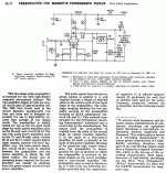
Have you carefully worked out the 2nd gain block's total bias? A 2 M grid to ground value will provide a fair amount of contact bias. Remember, 2.2 Mohms is the "classic" grid leak, AKA contact, bias value, with the cathode grounded.
Had a look at some 12AX7 data sheets and now I see what you're saying. I could always lower this value at the expense of some gain. Would affect the series resistor leading into the RIAA slightly as well. I've never (knowingly) biased a tube this way (cathode grounded and big grid leak).
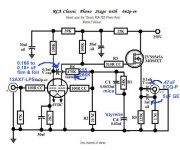
Grid stoppers and zener added:

I like to think I would have realized the grid stoppers were missing before building 😀
Last edited:
Move the protective Zener diode to the other side of the gate stopper, as that reduces the amount of metal that could serve as an antenna.
What you're doing is very similar to the tweaked RCA setup I'm associated with. Per Thorsten Lösch, I went with 100% grid leak bias in the 2nd gain block.
FWIW, 3.3 μF. is the absolute minimum value for the O/P coupler, if the 10 Kohm IHF "standard" load is to be driven.
What you're doing is very similar to the tweaked RCA setup I'm associated with. Per Thorsten Lösch, I went with 100% grid leak bias in the 2nd gain block.
FWIW, 3.3 μF. is the absolute minimum value for the O/P coupler, if the 10 Kohm IHF "standard" load is to be driven.
Attachments
Thanks, Eli. I realize that I'm reinventing the wheel here 🙂 Just challenging myself to do the calcs.
<snip>
I'm afraid I don't follow the bias question though. Is this referring to the DC coupling with the mosfet? If so, I'm kind of in the dark with mosfets and just stole this follower idea from you 🙂
He's referring to the bias on the second 12AX7 (I assume that is what it is), the 2M resistor provides plenty of contact bias for the second stage triode and the 1K unbypassed cathode resistor (not the best thing from a noise standpoint) can be deleted and the cathode connected directly to ground.
He's referring to the bias on the second 12AX7 (I assume that is what it is), the 2M resistor provides plenty of contact bias for the second stage triode and the 1K unbypassed cathode resistor (not the best thing from a noise standpoint) can be deleted and the cathode connected directly to ground.
I once saw this one tube pre 12AX7 phono schematic in Positive Feedback that did it more along the lines of my schematic though. This even used a 2.2M grid leak and a 1.2k cathode resistor though 😀
What you're doing is very similar to the tweaked RCA setup I'm associated with. Per Thorsten Lösch, I went with 100% grid leak bias in the 2nd gain block.
For the grid leak resistor on the 2nd stage 12AX7, what would be the minimum value resistor that would work there? 10M? 4.7M? 2.2M? Or is 20M really necessary?
I've never used contact bias before, and I don't have any 20M resistors on hand. I do have plenty of 10M, but only in carbon film (none in metal film, unfortunately).
--
I'm in the same boat and found some answers in the chart on the 2nd page of this data sheet:
http://www.mif.pg.gda.pl/homepages/frank/sheets/093/1/12AX7.pdf
Using grid-leak bias is a terrible idea as it makes the circuit far noisier, less consistent, and less predictable than ordinary cathode bias. It's 'useful' effect on RIAA accuracy is a laughable tradeoff. It's a gimmick.
Grid leak bias was used in days of old to allow the cathode to be grounded and so reduce hum from heater-cathode leakage. It was restricted to low signal levels from low impedance sources. These days we would use DC heaters.
Putting in a cathode resistor removes the only good reason for using grid leak bias.
The second stage of a phono preamp typically has a high source impedance (from the RIAA network) and slightly higher signal levels, so it seems a bad place to use grid leak bias.
Putting in a cathode resistor removes the only good reason for using grid leak bias.
The second stage of a phono preamp typically has a high source impedance (from the RIAA network) and slightly higher signal levels, so it seems a bad place to use grid leak bias.
Pretty standard design, actually. One of my colleagues in Israel who is possessed by anti-capacitance virus designed one with RL only, and an air variable capacitor on input.
Another friend who is more practical designed this one, I think it is a piece of an art:
What is the second tube: 6H6P?
Nobody about 6H6P?
I assume all resistors 1/4W?
Attachments
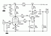
6N6P and 6H6P are two names for the same tube from what I can tell. Mu of 22 seems about right if the first tube is a pentode.
Sorry, I don't know. 0.5W is probably safe for most of them (depending on the bias). The load resistors for the pentode may need to be larger though (not familiar with this tube or how much current it usually draws).
I'm in the same boat and found some answers in the chart on the 2nd page of this data sheet:
http://www.mif.pg.gda.pl/homepages/f...93/1/12AX7.pdf
Thanks for that, good source of info. It looks like 10M is a traditionally used value for Rg if going for grid leak (contact potential) bias. But then...
Using grid-leak bias is a terrible idea as it makes the circuit far noisier, less consistent, and less predictable than ordinary cathode bias. It's 'useful' effect on RIAA accuracy is a laughable tradeoff. It's a gimmick.
Funny you should mention this.. I just read about that in your preamp book this morning! OK, I guess it's not hard to see how you feel about grid leak bias. 🙂 Duly noted.
Seems the trade-off is between high rp in the first stage 12AX7 causing RIAA inaccuracies from getting loaded down by the second stage's grid leak resistor (usually 1M), or if you try to fix that by going to a 10M grid leak and grid leak bias, you end up with the problems of noise, distortion, etc. from grid current in the second stage (as well as potentially low input impedance?).
--
Last edited:
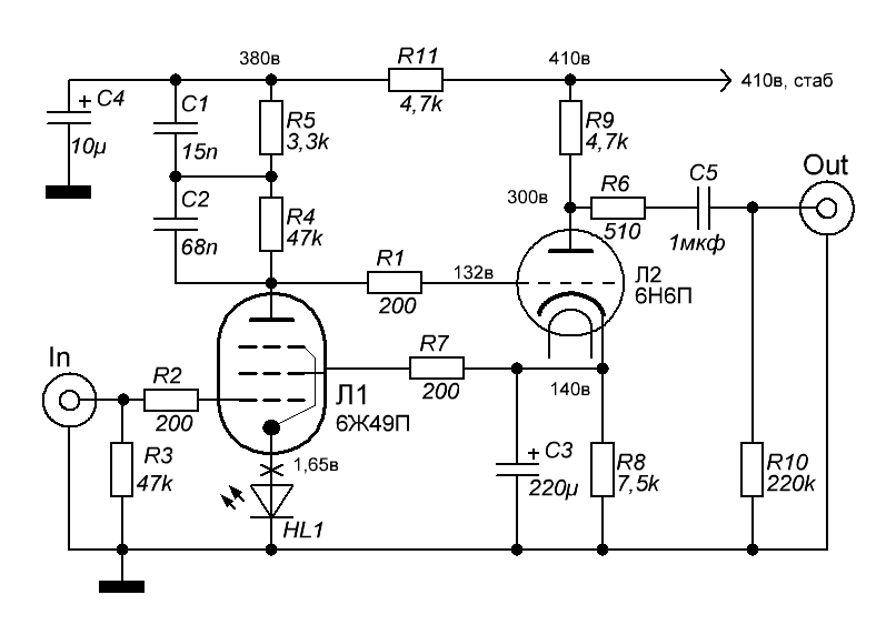
What about the resistors 0.5w 1w 2w?
6N6P is typically used with plate current higher than 5mA. Actually 15mA to 20mA is not uncommon. The 7.5k plate resistor will need to be much more than a 0.5W.
7500 ohms * 10mA = 75V dropped across Rp (plate load resistor)
75V * 10mA = 0.75 watts
I'd use a 3W resistor, minimum.
For tubes like 6N6P, 6N30P, 5687, ECC99, et al, I like to use wirewound 5W to 12W plate load resistors.
--
You need to look at the schematic and use the resistance values and voltages to figure out what current each tube is drawing.
Once you know the parts values, current, and voltages, then you use good old Ohm's Law to figure out how much power is being dissipated in each part.
6J49P:
Ebb = 380V
The plate load resistor is the sum of R5 and R4 in series, so
3300 + 47000 = 50300 ohms
The voltage at the plate of the 6J49P is shown as 132V on the circuit diagram. Therefore, there is 380 - 132 = 248V dropped across R4 and R5. Let's call it 250V, for convenience.
Ohm's Law says that if there is 250V dropped across 50300 ohms, then
248/50300 = 0.00497 A. We can round that up to 5mA, for convenience.
Kirchoff's Law says that the current will be the same at all nodes of the circuit. So, we can figure out how much voltage is dropped with 5mA going through each of R4 and R5.
R5 = 3300 ohms, so 3300R * 0.005A = 16.5V
R4 = 47000 ohms, so 47000R * 0.005A = 235V
(16.5V + 235V = 251.5V, which is still a good approximation for our purposes)
To find power dissipated in each resistor, voltage times current equals watts (power).
E*I = P
For the 3k3 resistor, 16.5V * 0.005A = 0.0825 watts. R5 can be a 1/4 watt part.
For the 47k resistor, 235V * 0.005A = 1.175 watts. R4 should be a 3W part.
For the 6N6P, its plate load resistor is 7k5 ohms, with 410V - 300V = 110V dropped across it.
110V/7500R = 0.014667A (14.67mA, or let's round that up to 15mA)
For R9, 110V * 0.015A = 1.65 watts, so I'd use a 5W part there.
There's 140V dropped across R8, so
140V * 0.015A = 2.1 watts, so a 5W part should be OK for R8.
And that's how I figure out the wattage rating of the resistors I need to use.
--
Last edited:

- Status
- Not open for further replies.
- Home
- Amplifiers
- Tubes / Valves
- Tube Phono Preamps