Another for the list:
http://tubecad.com/2016/04/17/Tube Phono Preamp 6N1P lg.png
from:
The Inverted Cascode
Had been thinking about CCDA and Cascode applications for phono pres recently just because it sounds fancy. Of course, JB already did it.
http://tubecad.com/2016/04/17/Tube Phono Preamp 6N1P lg.png
from:
The Inverted Cascode
Had been thinking about CCDA and Cascode applications for phono pres recently just because it sounds fancy. Of course, JB already did it.
Jdrouin, please keep us posted on what project you decide to build. I almost dropped the hammer on the PH16 myself a couple of months ago when tubes4hifi had their 10% off sale. What held me back was that I absolutely love building something from nothing more than a schematic and a pile of parts. The PH16 kit would've been quicker (and probably more accurate), but I'd have cheated myself out of a great building/learning opportunity. It looks like a great kit though. If it's anything like their ST70 kit, it's a winner. I don't think you'll go wrong if that's your choice.
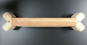
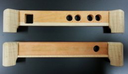
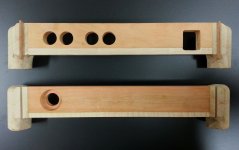
Here's a couple more pics of the chassis work so far. Sodacose: the first pic is for you; it reminded me of your tagline! 😀 I'ts really just test fitting the alignment of the splines by placing the front and rear panels together. The next two pics show the chassis rear (top) and front (bottom) from the outside and inside, respectively.
And moderators: please feel free to chunk my stuff into another thread if you feel the need.
Attachments
Got wood? Haha.
That's a very pretty start to your chassis. What kind of input/output jacks are you using?
Will follow the rest with interest!
That's a very pretty start to your chassis. What kind of input/output jacks are you using?
Will follow the rest with interest!
I knew you'd get the joke! Thanks for the kind words. The joints to the "feet" aren't as tight as I'd like, but this is my first build in over four(!) years. It's really just a fancy "burger box" (wooden chassis with aluminum top and bottom plates). The size of the four holes for the input/output jacks make it look as if I'm using XLR connectors, but they're really for these nifty Neutrik RCAs.
I'm using a shielded, filtered IEC power connector for the mains input, but otherwise the build will be pretty much identical to Jeff Yourison's in post #9. The plan is to divide the chassis into two sections, with the raw PS components taking up about 1/4 of the space. The remaining components will be installed inside a shielded aluminum sub-chassis. I haven't decided whether I'm going to stand the tubes up like Jeff did, or go for the streamlined look and mount them horizontally within the chassis. What do you guys say? Would exposed tubes nullify the shielding? Enquiring minds want to know!
I'm using a shielded, filtered IEC power connector for the mains input, but otherwise the build will be pretty much identical to Jeff Yourison's in post #9. The plan is to divide the chassis into two sections, with the raw PS components taking up about 1/4 of the space. The remaining components will be installed inside a shielded aluminum sub-chassis. I haven't decided whether I'm going to stand the tubes up like Jeff did, or go for the streamlined look and mount them horizontally within the chassis.
What do you guys say? Would exposed tubes nullify the shielding? Enquiring minds want to know! Tube shields are available, for very good reason. I like above chassis mounting, as ventilation is not an issue.
Those Neutrik jacks definitely have their uses. In addition to your situation, they can be used to replace old, closely spaced, connectors, without weakening sheet metal. The die cast housings are anything but flimsy. 🙂
You can improve the shielding of your enclosure by sticking copper tape to the internal wooden surfaces. Mouser stocks 3M and at least 1 other brand.
How about using sheet metal, or enclosure bottom panels by Hammond, etc, as a metal base on non conductive bases/plinths (very nice one above BTW).
I use tube shields as well for my preamps/phonos, incl. 6dj8s, 12AX7s and such, that are mounted above. They are aluminum but a little bit of shielding is better than none? Anyway, be careful since working with sheet metal without correct tools is a nightmare, so, YMMV/caveat emptor, etc., i have scars to prove it.
I use tube shields as well for my preamps/phonos, incl. 6dj8s, 12AX7s and such, that are mounted above. They are aluminum but a little bit of shielding is better than none? Anyway, be careful since working with sheet metal without correct tools is a nightmare, so, YMMV/caveat emptor, etc., i have scars to prove it.
Thanks for the copper "tape tip", Eli. Why didn't I think of that? The Neutrik connectors were purchased because I didn't want to go through the whole process of machining yet another piece of aluminum for the rear plate, only to be faced with carving a matching recess for mounting it on the wooden back panel. Besides, they just look so good; they're likely the last word in RCA "jackdom" before the step up to XLR.
Thewwwall: your ideas on metalwork are all good ones - especially those regarding safety. I usually use an old pair of Kevlar gloves when cutting sheet metal.
Thewwwall: your ideas on metalwork are all good ones - especially those regarding safety. I usually use an old pair of Kevlar gloves when cutting sheet metal.
Great Work!!
Mr_Zenith
Your wood working ability shines through.Please keep us informed of your build.If only they were 3D!
PS What HV Reg is that?........Schematic please
Mr_Zenith
Your wood working ability shines through.Please keep us informed of your build.If only they were 3D!
PS What HV Reg is that?........Schematic please
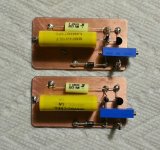
Hi pl802, and thanks again for the kind words. The pic above is of the two 250 VDC regulators in the upper right of the schematic in post 4 of this thread (I'd repost it here, but I'm replying via my phone). My ultimate goal for this build is to construct each subassembly on its own ground plane using punched PC board "islands". This is called "Manhattan" style construction, for those unfamiliar with amateur radio homebrewing technique. Pete Millet has built a couple of amps using this basic idea, except he used proper insulated terminals (in other words, he didn't "cheap out" like I did!). 😀
PS What HV Reg is that?
I suspect Mr. Z. is using this schematic. The data sheet for the TO92 case LR8 is here.
Just finished the HV regulators for Eli's phono stage, built "Manhattan" style. This is my first time using real solid-state devices for tube equipment, so please speak up if anybody sees anything stupid! 😀
I love the Manhattan style of builds: they look like mini-architecture. And you get the benefit of the ground plane.
Those Neutrik jacks definitely have their uses. In addition to your situation, they can be used to replace old, closely spaced, connectors, without weakening sheet metal. The die cast housings are anything but flimsy. 🙂
How about they can also be mounted below the chassis for extra shielding?
Mr_Zenith, your Duttman/RCA build looks fantastic! Can't wait for you to tell us how it sounds.
Life has intervened, and I'll likely need to wait until June or July to start making component purchases, so I'm still thinking about it.
If I could pose another question to interested parties: which projects that have been (or have not yet been) recommended would have the classic tube "sweetness" that some of us like?
My frame of reference is the George Wright WPP100C, which I heard driving a pair of Wright 300B mono blocks designed to sound more like a 2A3 (a one-off that he seems to have later developed into the WPA Mono 7). The sound quality had this incredible liquidity and a kind of sweetness without sacrificing microdetail or soundstage or any aspects of "fidelity." It was involving, bewitching, the "SET magic," yadda yadda yadda. I like my Tubelab SE 300B a lot but it doesn't do that -- yet.
So, has anyone ever tried to emulate (or duplicate) the WPP100C?
Here’s what the “Tech Talk” page of George’s site had to say about the WPP100C in 2002:
*********************
From: Wright-Sound - Products Listing
Tube Compliment
* 2 x 5963
* 4 x 6ER5/EC95
* 1 x 6EA7/6EM7
* 1 x 6X4
Specifications
* Frequency Response: Better than 20 Hz to 20 kHz, plus/ minus 1 dB RIAA curve
* Distortion: Less than 0.4 percent total harmonic distortion
* Input Impedance: 47 kilohms
* Output Impedance: 2 kilohm, nominal; will drive loads down to 600 ohms with some loss of output level
* Voltage Gain: 0-60 dB, nominal
From: Wright Sound - Tech Talk
"The phono cartridge jack is coupled directly into the grid of the first stage. The cathode is bypassed by a small capacitor paralleled with a large value filter to bring the cathode reactance as close to ground as possible. The frame element is tied directly to ground, and the plate is coupled through a capacitor into the passive RIAA equalizer circuit into the next stage grid. The cathode and frame are hooked up as in the first stage… the second phono stage is capacitor coupled directly to the linear level potentiometer.”
The WPS04 power supply is described as follows:
"The power supply uses a full wave tube rectifier through a double Pi filter into the series pass inverting regulator stage. DC output is then fed back through a control stage and back up to the series regulator. This reduces noise and keeps the DC constant throughout it's operation. The filament uses fast recovery diodes with slow start circuitry driving into a large filter capacitor to provide a clean filament source... The WPL10V and WPP100B/C use a cannon XLR-type 4 pin inter-connection with a shielded DC cable to keep noise away from the preamp chassis.”
*********************
There is also this thread on Audiogon, which reproduces some emails from George discussing component selection and aspects of the circuit:
https://forum.audiogon.com/discussions/6er5-tube-question-wright-wpp-100-phono-stage
Basically, I was thinking I could take the circuit features described here and try to design something (the double pi filter, for instance, is a mod I've already done in my Tubelab SE without realizing what it was called). I haven't been able to find gut shots of the WPP100C or its WPS04 power supply, so I'd use some circuit design software to try and come up with a feasible alternative in hopes that it sounds like the Wright.
Fool's errand?
Or, I could just try to learn what circuit features and components lead to the sound characteristics I like and design from scratch. Any source/reading recommendations for that?
Jdrouin, please keep us posted on what project you decide to build.
Life has intervened, and I'll likely need to wait until June or July to start making component purchases, so I'm still thinking about it.
If I could pose another question to interested parties: which projects that have been (or have not yet been) recommended would have the classic tube "sweetness" that some of us like?
My frame of reference is the George Wright WPP100C, which I heard driving a pair of Wright 300B mono blocks designed to sound more like a 2A3 (a one-off that he seems to have later developed into the WPA Mono 7). The sound quality had this incredible liquidity and a kind of sweetness without sacrificing microdetail or soundstage or any aspects of "fidelity." It was involving, bewitching, the "SET magic," yadda yadda yadda. I like my Tubelab SE 300B a lot but it doesn't do that -- yet.
So, has anyone ever tried to emulate (or duplicate) the WPP100C?
Here’s what the “Tech Talk” page of George’s site had to say about the WPP100C in 2002:
*********************
From: Wright-Sound - Products Listing
Tube Compliment
* 2 x 5963
* 4 x 6ER5/EC95
* 1 x 6EA7/6EM7
* 1 x 6X4
Specifications
* Frequency Response: Better than 20 Hz to 20 kHz, plus/ minus 1 dB RIAA curve
* Distortion: Less than 0.4 percent total harmonic distortion
* Input Impedance: 47 kilohms
* Output Impedance: 2 kilohm, nominal; will drive loads down to 600 ohms with some loss of output level
* Voltage Gain: 0-60 dB, nominal
From: Wright Sound - Tech Talk
"The phono cartridge jack is coupled directly into the grid of the first stage. The cathode is bypassed by a small capacitor paralleled with a large value filter to bring the cathode reactance as close to ground as possible. The frame element is tied directly to ground, and the plate is coupled through a capacitor into the passive RIAA equalizer circuit into the next stage grid. The cathode and frame are hooked up as in the first stage… the second phono stage is capacitor coupled directly to the linear level potentiometer.”
The WPS04 power supply is described as follows:
"The power supply uses a full wave tube rectifier through a double Pi filter into the series pass inverting regulator stage. DC output is then fed back through a control stage and back up to the series regulator. This reduces noise and keeps the DC constant throughout it's operation. The filament uses fast recovery diodes with slow start circuitry driving into a large filter capacitor to provide a clean filament source... The WPL10V and WPP100B/C use a cannon XLR-type 4 pin inter-connection with a shielded DC cable to keep noise away from the preamp chassis.”
*********************
There is also this thread on Audiogon, which reproduces some emails from George discussing component selection and aspects of the circuit:
https://forum.audiogon.com/discussions/6er5-tube-question-wright-wpp-100-phono-stage
Basically, I was thinking I could take the circuit features described here and try to design something (the double pi filter, for instance, is a mod I've already done in my Tubelab SE without realizing what it was called). I haven't been able to find gut shots of the WPP100C or its WPS04 power supply, so I'd use some circuit design software to try and come up with a feasible alternative in hopes that it sounds like the Wright.
Fool's errand?
Or, I could just try to learn what circuit features and components lead to the sound characteristics I like and design from scratch. Any source/reading recommendations for that?
Many of the good phono stages here are over in analog source where you'll find the Salas phono stage, several by Koi Farm, and at least 4 by yours truly. I am a bit puzzled by the fact that most members never ever recommend designs by fellow members. There are some good ones here. (the examples here are all tube or tube/hybrid)
As Kevin wondered about that use of 'alien designs' I remembered a schematic proposed by Thorsten Loesch (by his funky eastern alias) some years ago. I think the thread is listed under 'DC Phono', or somesuch. And, as builders chimed in, the phono stage sounded quite good.
Kind regards, Stef.
The link; dc phono
Last edited:
Been working on a phono design lately. I'll just leave it here 🙂

Values chosen to be easy to find and all within about 1% of what I'm calculating to be ideal.
Values chosen to be easy to find and all within about 1% of what I'm calculating to be ideal.
Add a 510 ohm CC gate stopper and a 12 V. protective Zener diode to the FET. 100 ohm CC grid stoppers on the 'X7 sections is (IMO) good prophylaxis.
Have you carefully worked out the 2nd gain block's total bias? A 2 M grid to ground value will provide a fair amount of contact bias. Remember, 2.2 Mohms is the "classic" grid leak, AKA contact, bias value, with the cathode grounded.
Have you carefully worked out the 2nd gain block's total bias? A 2 M grid to ground value will provide a fair amount of contact bias. Remember, 2.2 Mohms is the "classic" grid leak, AKA contact, bias value, with the cathode grounded.
Thanks, Eli! Totally forgot to add in stoppers. 510 for the mosfet it is. I'll add a Zener as well.
I'm afraid I don't follow the bias question though. Is this referring to the DC coupling with the mosfet? If so, I'm kind of in the dark with mosfets and just stole this follower idea from you 🙂
I'm afraid I don't follow the bias question though. Is this referring to the DC coupling with the mosfet? If so, I'm kind of in the dark with mosfets and just stole this follower idea from you 🙂
Pretty standard design, actually. One of my colleagues in Israel who is possessed by anti-capacitance virus designed one with RL only, and an air variable capacitor on input.
Another friend who is more practical designed this one, I think it is a piece of an art:
What is the second tube: 6H6P?
- Status
- Not open for further replies.
- Home
- Amplifiers
- Tubes / Valves
- Tube Phono Preamps