Wow, ClefChef - excellent work! 
I'm a bit surprised there haven't been any comments to that effect in the past three or so days, but I'm happy to be the first to say, "nice job".
Thanks for the insight, Kevin. I never actually stopped to think about those advantages. That's likely because most such designs I've seen have either been used with some incarnation of the tired old RCA circuit [I don't count Eli's version as one of those], or some other more questionable design. I had no idea the batteries would last so long, either; I was thinking a maximum of maybe 4 to 6 months.
Anyway, for me, that's what this forum is about - learning. I've done a few scratch builds, but I'm not what you'd call an expert by any stretch of the imagination. 😕 And I'm always grateful for all that I've learned here - and for the folks here as well.
I'm a bit surprised there haven't been any comments to that effect in the past three or so days, but I'm happy to be the first to say, "nice job".
In my designs the batteries generally outlast the tubes used. I replace at 2 - 4 year intervals. (Some brands of A22/A23 batteries do not seem to last quite as long) Quiet source of bias voltage (floating if necessary) and in the case of mu followers allows for some interesting design flexibility in setting operating points and achieving a high effective load impedance on the driving stage.
Thanks for the insight, Kevin. I never actually stopped to think about those advantages. That's likely because most such designs I've seen have either been used with some incarnation of the tired old RCA circuit [I don't count Eli's version as one of those], or some other more questionable design. I had no idea the batteries would last so long, either; I was thinking a maximum of maybe 4 to 6 months.
Anyway, for me, that's what this forum is about - learning. I've done a few scratch builds, but I'm not what you'd call an expert by any stretch of the imagination. 😕 And I'm always grateful for all that I've learned here - and for the folks here as well.
Batteries definitely have their place in my arsenal of design tools, along with all sorts of other sometimes outlandish things.. lol
During one BAF Scott Wurcer described his microphone in which he used opto-couplers as sources of a voltage. He connected a string of them to get polarized voltage for the capsule. But you can use them in tube amps, powering the LED as a cathode load, and using it as a floating source of a voltage.
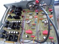
Wow, ChefChef, what a gorgeous build. Glad to hear it's working well for you. Thanks for the sharing the component types you used.
I'm thinking about switching to an MC cartridge and using a pair of step up transformers with this phono stage. Assuming the power supply is shielded in a separate chassis, is it OK to build the SUTs into the chassis of the RIAA stage, or should they be in their own separate, shielded chassis?
I was thinking that building them into a separate chassis runs the risk of signal degradation through the additional RCA connections, but wasn't sure if there'd be an issue including them in the same box as the RIAA components and tubes.
You're already going to do everything you can to keep the RIAA box as quiet/hum-free as possible, so putting them in that box makes sense to me. It would also simplify your grounding scheme.
On the other hand, if you plan to switch back and forth between MM and MC, making it more modular is appealing. Some simple switching would also solve this if all-in-one.
On the other hand, if you plan to switch back and forth between MM and MC, making it more modular is appealing. Some simple switching would also solve this if all-in-one.
Thanks, Sodacose. Yes, I was thinking about putting the SUTs inside the RIAA chassis and adding a simple switch to connect to the input and output sides of the SUTs, in order to be able to toggle between MM and MC.
I was wondering whether the switch would add its own signal degradation.
I was wondering whether the switch would add its own signal degradation.
Well, audibly. The more I work with this stuff, the more I realize there's nearly as much art as there is science, so having the best numbers doesn't necessarily mean having the best sound (though good numbers are important).
The purist way of course would be to make a dedicated MC or MM phono pre, but I imagine a toggle switch for turning the SUT circuit on/off would be fine as long as the signal wires are soldered together well on the switch tabs.
The purist way of course would be to make a dedicated MC or MM phono pre, but I imagine a toggle switch for turning the SUT circuit on/off would be fine as long as the signal wires are soldered together well on the switch tabs.
It's a good question, really. I don't have the experience to answer it though. You would have to change the load characteristics depending on what kind of cartridge you use as well, so a simple switch is more than it sounds.
I think a lot of the commercial amps that have this kind of switch are using an opamp for that first stage and so they're switching the gain level, not the input routing.
Some relevant reading on Thomas Mayer's site:
VinylSavor: MC step up transformer with selectable gain
SY would be a good person to weigh in on this. Paging Dr SY!
Switches in mV. signal lines are (IMO) best avoided. However, they can be made to work. A top quality, sealed, part, with coin silver contacts should get the job done. That's a far cry from the slide switches used in "vintage" units, which (I very strongly believe) must go. A 3PDT "on-on" toggle switch is what I would use. Ground all 3 "central" terminals, to shield the channels from each other.
A cartridge trafo that comes inside a metal shielding can will be quite satisfactory inside the RIAA circuitry's chassis. Sowter's model 9570 is such a part. CineMag and Jensen should have suitable stuff, too.
A cartridge trafo that comes inside a metal shielding can will be quite satisfactory inside the RIAA circuitry's chassis. Sowter's model 9570 is such a part. CineMag and Jensen should have suitable stuff, too.
ClefChef. More info please!
You have built exactly what I was thinking of building. A friend built the Tubecad Tetra phono stage built it sounds a bit cold blooded, he couldn't really engage with it. It sounds like your experience with the Aikido phono was just the opposite.
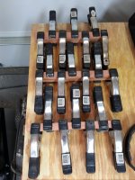
If you don't mind me asking, where did you get the cabinets? What parts did you substitute form the ones supplied in the kit? As well what is (are) the stack of black cabinets in one of the photos.
TIA Steve
You have built exactly what I was thinking of building. A friend built the Tubecad Tetra phono stage built it sounds a bit cold blooded, he couldn't really engage with it. It sounds like your experience with the Aikido phono was just the opposite.
If you don't mind me asking, where did you get the cabinets? What parts did you substitute form the ones supplied in the kit? As well what is (are) the stack of black cabinets in one of the photos.
TIA Steve
Switches in mV. signal lines are (IMO) best avoided. However, they can be made to work. A top quality, sealed, part, with coin silver contacts should get the job done.
'Dry circuit' switches and relays normally use gold contacts, not silver. You will sometimes see contacts specified as gold over silver because it allows distributors to sell the same item for dry circuit and power circuit applications. In a power circuit, the thin gold layer burns off immediately and leaves the thick silver substrate, which has good power switching life.
Makes sense. Then there are mercury wetted reed relays, but a builder gets circuitry complications and a toxic substance.
Lundahl as well, many have mu metal shields and are quite tolerant of stray magnetic fields... I strongly recommend not putting a switch in the path of a low output MC and using dedicated RCA jacks (or lemo if you want to go balanced) directly to the primary of the SUT. The switch would be on the secondary side and select between MM and MC cartridge inputs.
Look for switches with maximum contact ratings of 0.4VA or 10mA which indicates they are intended for low level signal switching. (As noted above these always have gold plated contacts. I know from experience that silver does not work.)
Eli's suggestion to use a 3pdt switch is an excellent one, not always available. I consider spdt switches perfectly acceptable - one per channel.
None of my cartridges produce more than 300uV @ 5cm/sec so I am careful. I use LL1941 in a nice aluminum box and keep the grounds separate for each channel and have a separate box ground which usually also serves for arm ground. No hum problems. I have 2 of these and a multi-tan IC based head amp a friend made for me a couple of years ago - I generally prefer the transformers.
Erno Borbely EB-1195-221 is an outstanding tube phono with cascoded J-Fet input . Low noise, open, dynamic with great low level details,better than Pass Xono clone which I also built.I am not tube fanatic, but this preamp shows all the LP potential.
This phono preamp is better than many popular DIY projects. Dual mono, every gain stage has its own low noise regulator. Heater PS is also dual mono with soft start to save filaments. Transformers are in separate enclosure. Zero hum and noise even with 0.2mv cartridge.High overload, passive RIAA.
Attachments
Thanks again everyone for the advice on projects and switching. Right now I'm leaning toward the VTA PH16 for its 0.2% RIAA accuracy, no feedback, well thought out loading options for a variety of cartridges, buffer stage to prevent interaction with the amplifier, and builder reviews that indicate wonderful musicality, detail, and a huge soundstage.
I'm still considering other projects -- including the Russian ones or trying to design something similar to the Wright WPP100C -- because people indicate the PH16 does not have that tube "sweetness," which is something I like.
At any rate, here's a roundup of the projects that have been linked in this thread:
* VTA PH16
* Glassware Tetra Sans PS (I'd use the Janus or PS-1 power supplies)
* Glassware PH-1 (Janus or PS-1 power supply, or dual mono with one PS-5 per channel plus two self-designed heater supplies)
* Bottlehead Seduction or Reduction (new or used)
* I have Kevin Kennedy's 1-tube and 2-tube per channel designs.
* Eli Duttman's modded RCA phono circuit and power supply (also here)
* TCJ Remake of the RCA phono circuit
* Eric Barbour Planar-Triode Phono Pre
* A list of Russian projects
* Jeremy Epstein's 6C45P
* Valve Itch phono
* His Master's Noise: A Thoroughly Modern Tube Phono Preamp
* The "Muscovite" 6S3P Tube Phonostage
* The Muscovite Mini III (6N23P) Phono Stage
* Mini-Me phono preamp
* Mini-Me second edition tube phono preamp
* 6Z4P(6AU6) pentode DC-coupled to a 6N30P
* Coleman Shunt Cascode RIAA
* A Russian design linked by Wavebourn
* The "fonojunior" linked by Waltube (position values here)
* A 6DJ8 project posted by lexx21 (he prefers 6N23P instead, LR8 regulators on the high voltage and DC filament supplies)
* Les Box MK III
* Erno Borbely EB-1195-221
Step-UP Devices
* SUT with selectable gain
* Sowter 9570
* Lundahl

I've gotta say thanks to everyone here for a most inspiring thread. The wealth o' knowledge on this forum as a whole is incredible enough, but seeing the builds from Jeff Yourison and ClefChef has pushed me further into the depths of my disease and given me the itch to, well... build. I've constructed a small boatload of' power amps plus one preamp in the past, but I've never tackled a phono stage before. You guys have given me the "stones" (aka "testicular fortitude") to try.
What's also goaded me into action is the fact that the only phono stages I own are (1) an unrestored RIAA section in an old Harman Kardon "Ballad" integrated, ca. 1959, and (2) another unrestored jewel in the form of a Dynaco PAS3, which screams for mercy at every switch-on. 😀 The HK unit is basically sound, but the electronics are just noisy - mainly too many 50-plus-year-old slider switches in the signal path. As for the old Dynaco? Well, it is what it is. I think I can do better.
Eli's modified RCA circuit is appealing for several reasons. First, it seems relatively simple for a not-so-newbie to build and troubleshoot. It's also proven; I've read many kind words regarding this design here and on other forums. The combination of tubes and solid state (Tubelab's "sand-based life forms") is intriguing to me. And finally, it's relatively economical for a DIY build (boy, do the parts add up!).
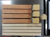
So while waiting impatiently for the parts to arrive, I decided to get cutting on the chassis. The first pic shows cherry stock for the front and sides being clamped during bookmatching. The second pic shows the basic chassis parts. The curly maple strips are trim for the cherry front, back and sides. The three curly maple blocks are for the feet; they'll be cut to the same dimensions as the part to the right that looks like "home plate".
What's also goaded me into action is the fact that the only phono stages I own are (1) an unrestored RIAA section in an old Harman Kardon "Ballad" integrated, ca. 1959, and (2) another unrestored jewel in the form of a Dynaco PAS3, which screams for mercy at every switch-on. 😀 The HK unit is basically sound, but the electronics are just noisy - mainly too many 50-plus-year-old slider switches in the signal path. As for the old Dynaco? Well, it is what it is. I think I can do better.
Eli's modified RCA circuit is appealing for several reasons. First, it seems relatively simple for a not-so-newbie to build and troubleshoot. It's also proven; I've read many kind words regarding this design here and on other forums. The combination of tubes and solid state (Tubelab's "sand-based life forms") is intriguing to me. And finally, it's relatively economical for a DIY build (boy, do the parts add up!).
So while waiting impatiently for the parts to arrive, I decided to get cutting on the chassis. The first pic shows cherry stock for the front and sides being clamped during bookmatching. The second pic shows the basic chassis parts. The curly maple strips are trim for the cherry front, back and sides. The three curly maple blocks are for the feet; they'll be cut to the same dimensions as the part to the right that looks like "home plate".
Attachments
- Status
- Not open for further replies.
- Home
- Amplifiers
- Tubes / Valves
- Tube Phono Preamps