I'm curious . . . have you ever tried battery bias? Either on the cathode using a rechargeable battery or on the grid using a regular (alkaline or lithium) battery?That's an idea - I've done that before but can't remember the results, it was years ago.
I have a modular system of top plates which allows me to kind of breadboard circuits pretty quickly, so I just run through a variety of options and listen to them for anything that sounds good. It needs a valve that sounds pretty good for starters, and then some way of optimising the operating point and the circuit topology. Active loads have never made it into my ballpark of sounds I want to listen to, still waiting for that to happen. Plate chokes can be good - they stay on the list.
A resistor load can be good, so that stays on the list. Ideally I want an unbypassed cathode resistor but it gets too big unless you add a diode or two into the mix. Alternative is to add a bypass cap, but if you can get away with a diode it's useful. I combine a diode with a series resistor because that sounds smoother to my ears. I'm liking what I have at the moment and it makes it into the ballpark of circuits I'm happy to listen to in my system. The E180CC has the right kind of gain and it works quite nicely. For a sensitive system the E80CC is another valve I like with a diode+resistor, same idea. And some of the old European radio valves like the MH4 which was mentioned earlier on. Mu of either is around 30 though, and Rp around 11-12K so using a resistor load it would need a preamp in an average system. Not a commercial choice at all.
View attachment 1044313
As many of your experiments as I've read about over the years, I've never heard you mention it.
I did at one point but not recently. Why - do you like it?I'm curious . . . have you ever tried battery bias? Either on the cathode using a rechargeable battery or on the grid using a regular (alkaline or lithium) battery?
As many of your experiments as I've read about over the years, I've never heard you mention it.
Yes, although I can't say that I've done any real A-B comparison. Since you're trying various bias schemes on your input tubes, I'd certainly suggest that you give them a listen.I did at one point but not recently. Why - do you like it?
I originally tried using battery cathode bias on an amp that had 27s as input tubes. Under normal use, the current being drawn should keep them charged up. But, since I have numerous amps, there are times when they might not be used regularly and the rechargeable batteries would lose their charge. I got tired of having to remove them and put them on a charger so I switched to using battery grid bias.
On the grid, they just provide a reference voltage (perhaps that's not the technically correct term) unless the tube is drawing grid current. It's just fixed bias that's not adjustable. As a result they last as long as their shelf life which, in the case of lithiums, may be up to 10 years.
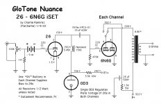
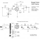
In my 1626 preamp I use a single 9v to bias the two tubes, a configuration which requires DC blocking caps on the input. In my recent "inverted SET", the Nuance, I use one 9v for each 26. That configuration, where the battery is in series with the grid, allows you to eliminate the DC blocking caps. When I had it breadboarded I tried both and I couldn't hear any difference but I went with the individual batteries and no caps option, just on general principle.
Anyway, you might give it a try. Maybe you'll like it, maybe not.
Attachments
Last edited:
I seem to be traveling in the same circles as FlaCharlie and andyjevans these days. 🙂
Today I was looking for information sources on circuit design using plate chokes (Hammond 156C) on a DHT input tube (26, 30) for a 6N6G SET amp, and this thread happened to be at the top of the Tubes/Valves forum. I've seen several variations of Charlie's circuit by now. So, I'm searching the web, but if anyone has good sources on the theory and practice of using plate chokes on an input tube, I'd appreciate it.
I don't really want the hassle of batteries, or to put them in the signal path. Seems the easiest way (for me, at least) would be to use plate chokes and cathode bias, rather than grid bias, but maybe grid bias is necessary? I want to understand before I proceed.
Also, I'm wondering how one draws a loadline on the tube datasheet with choke (rather than resistor) plate load? Additionally, if you're using a 0D3 gas regulator tube, like Charlie, then do you draw the loadline to the 156V coming off the VR tube or does the #26 "see" the voltage before the 0D3 as the supply voltage (e.g. 242V)?
If you are going to use an 0D3 you need to read up on how to use it. The resistor size is important, plus its wattage. And the 0D3 has to be connected so the HT only reaches the valve when the 0D3 is in its socket. Bypass cap around the glow tube should be no more than around 0.047uF and no big cap after the glow tube. It's all in the instructions for using glow tubes.
https://frank.pocnet.net/sheets/141/g/GL874.pdf
I've been listening to 2 156C in series for a few days and though it works, other more sophisticated chokes have better tonality - at a price. So I went back to a resistor load in the end for neutrality and tone. Anode chokes are much happier with valves with lower Rp. So don't ignore a 2a3 or 6B4G as your DHT if it has enough gain. When I've tried it as a preamp tube I thought the sound was excellent. And an anode choke of 50H would be fine and should have much lower DCR. You could even try a pair of Hammond 157G or 126B.
I'm not very technically astute, so I can't really help you with most of those questions.I seem to be traveling in the same circles as FlaCharlie and andyjevans these days. 🙂
Today I was looking for information sources on circuit design using plate chokes (Hammond 156C) on a DHT input tube (26, 30) for a 6N6G SET amp, and this thread happened to be at the top of the Tubes/Valves forum. I've seen several variations of Charlie's circuit by now. So, I'm searching the web, but if anyone has good sources on the theory and practice of using plate chokes on an input tube, I'd appreciate it.
I don't really want the hassle of batteries, or to put them in the signal path. Seems the easiest way (for me, at least) would be to use plate chokes and cathode bias, rather than grid bias, but maybe grid bias is necessary? I want to understand before I proceed.
Also, I'm wondering how one draws a loadline on the tube datasheet with choke (rather than resistor) plate load? Additionally, if you're using a 0D3 gas regulator tube, like Charlie, then do you draw the loadline to the 156V coming off the VR tube or does the #26 "see" the voltage before the 0D3 as the supply voltage (e.g. 242V)?
All I can say about battery bias is try it and use it if you like it, or use something else, but you never know if you'll like it unless you listen. YMMV, as always.
I was also skeptical about using the battery in the signal path but I couldn't hear any difference. To me, the appeal of using battery grid bias of either type with the 26 (or other DHT) is that the two input tubes can share the same filament supply.
As far as I know, if you use any type of bias that involves the "cathode" of a DHT you need to heat the filaments with separate supplies.
As for the 156C, it's inexpensive and it seems to work fine within its current limits. I used it because I was advised that I would get a bit more drive with it than I would if I used a resistor load. When I had the amp breadboarded, I tried using two in series and I thought a single one sounded a little better. I don't have any experience with other plate chokes, as Andy does. His experience with them is fairly extensive so I'm sure he can offer some solid, practical, advice.
I do know that the better plate chokes range from more expensive to much more expensive and I build low budget / bang for buck stuff using junkbox parts whenever possible. So my approach is totally different from most everyone who posts on this forum.
Andy is correct that VR tubes like the 0D3 should be wired so that if the tube is removed the HT is cut off. There's a jumper in the tube that connects between two of the pins. You just run the supply through it and then connect the output side to the VR tube's plate. That way, if the tube is removed, it cuts off the HT. I did this but didn't include it in my schematic. Details are in the data sheet Andy linked.
I should say that the only reason I used a VR tube was because I'd never used one before and wanted to give it a try. I have no idea if it offers any technical advantage or drawback. I do like the way it looks and it works fine. I suspect it's somewhat superfluous.
Putting aside the technical wrangling of getting the VR tube to work and related safety, does anyone have any experience regarding the sonic impact of using a VR tube for bias duties?
No experience with using a Gas VR tube for Bias Duty.
Question:
Bias for what kind of circuit?
Negative Grid Bias for the output tube(s)?
Bias for the screen of an input tube?
Etc?
I expect that any sonic impact could be different, for different circuits.
Any noise of a Gas VR tube used for an input or early stage would be amplified, but less likely to be an issue for an output stage.
Just my thoughts.
Negative Fixed Bias for an output tube. Just hate the idea of using any sand and thought a VR tube might (not sure) be a stable and quiet DC source. I dont have any VR experience, so I could be off base.
I made a little neg bias board similar to the circuits this page. Works like a charm. With adjustable bias, an adjustable CCS load, and Rod’s adjustable heaters, I can sweep through the full range of operating points for a variety of DHTs.
I can totally relate to Andy's subjective impressions about the sound. Although, I am yet to hear a choke that sounds better than the CCS, though I have not heard any good chokes to be honest. Andy, I also prefer the CCS connection to the mu connection--it sounds more open to me. Also slightly prefer the CCS over the gyrator--it is simpler and sounds as good or better to my ears.
I am going to make a board with adjustable negative bias (like the one below), adjustable CCS, and adjustable heaters. Then we can have some fun.
Looks like we will have to wait a while yet before we get the 'hearability' report of a double blind test on plate loads.
Then we will get a report on which distortion sounds best. And to which participant in the study. 😀
Then we will get a report on which distortion sounds best. And to which participant in the study. 😀
Could you post your CCS circuit? Or send it to me in a PM? I'm always interested in trying new circuits. We seem to be thinking along the same lines.I can totally relate to Andy's subjective impressions about the sound. Although, I am yet to hear a choke that sounds better than the CCS, though I have not heard any good chokes to be honest. Andy, I also prefer the CCS connection to the mu connection--it sounds more open to me. Also slightly prefer the CCS over the gyrator--it is simpler and sounds as good or better to my ears.
It is the tried and tested CCS with a pair of depletion mode FETs. See figure 5 here.
https://www.diyaudio.com/community/...a-thoroughly-modern-tube-phono-preamp.163570/
https://www.diyaudio.com/community/...a-thoroughly-modern-tube-phono-preamp.163570/
banpuku,
Negative bias for an output tube, and no sand in the circuit.
How much voltage?
You can use 6AL5 Twin Diode vacuum tube, and a few parts to make an excellent negative bias supply.
For Example:
A 50V center tapped secondary, a 6AL5, and a CRC filter will put out more than 60V negative bias.
A potentiometer (or 2 fixed resistors), will provide a portion of the 60V, as needed by the output tube.
Note: If the B+ of the output tubes is unregulated, then as your power mains voltage goes up and down:
your B+ goes up and down by the same percentage as the power mains voltage;
and the negative bias also goes up and down by the same percentage as the power mains voltage:
Power mains goes up from 120V to 122V
B+ goes from 360V to 366V
Negative bias goes from -60V to -61v
They roughly track. For a Triode or Ultra Linear output stage, the plate current remains approximately the same.
Just my opinions
Food for thought:
No Silicon Solid State devices is one thing.
Many Vacuum Tubes have Silicon . . . the Glass Envelope

6A3sUMMER, thanks again for the help. I have a 0-70Vac secondary, so wont be able to use the center tap solution with the 6AL5. I am trying to get 50-60V fixed bias on a GM70 output tube, and thus why I was looking into a VR tube solution. Maybe I am overthinking this and should just us an Shotky rectifier + LCR.
banpuku,
6AL5, OK
A 0-70V secondary works with a 6AL5 (with plates tied together or not).
Of course you need 6.3V to run the 6AL5 filament.
70V rms is 100V peak, and the 6AL5 drops 10V or less from that.
Without a center tap, it is half wave rectification, just like many other amplifiers grid bias.
Most of those amplifiers use either selenium rectifiers, or silicon rectifiers, both are solid state / sand.
So use the 6AL5 and get rid of selenium and/or silicon.
Again, use a CLC filter; and a potentiometer or 2 resistor divider to get the 50 - 60 Volts that you need.
Or . . .
VR tube, OK
If you want to use a VR tube, you can use a resistor from the amplifier B+.
OA3, OA3A, OC2 for 75 Volts
OB3, OB3A for 90 Volts
OB2, OC3, OC3A for 105 Volts
Use a potentiometer, or 2 resistor divider across the VR tube to get the 50 - 60 Volts that you need.
- Home
- Amplifiers
- Tubes / Valves
- Tube input stage - plate choke or active load?