My 40W output power expectations at a2 mode are based on practical observations of matched input and output sone waves. Input wave from tube sine wave generator with 120V RMS showed no visual difference from the output sine wave with 5 Ohms resistive load attached
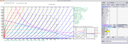
Look at the static load line for 40W output.
(In dynamic load at LF and HF it will be worst...)
because the working ellipse will "crush" deeply into X axes and hardly will be deformed.
The diference in Ri in extreme points are huge, causing dramatic deferent behaviour of OT in +half period and -half period signal at anode.
That will additionaly correspond with current flow G1 in + half periode input signal.
Because +20V=5mA, +60V=14mA, so Iti will be significant at +80V of Ug when input signal raching max for max power...
Off-course input signal for the theoretical 40W is 420Vp-p.
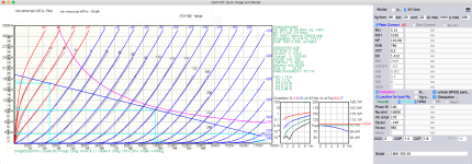
I will simulate for minimal primary inductance and max capacitance at the 20Hz and 20KHz
with dynamic load lines to see what is happening.
(In dynamic load at LF and HF it will be worst...)
because the working ellipse will "crush" deeply into X axes and hardly will be deformed.
The diference in Ri in extreme points are huge, causing dramatic deferent behaviour of OT in +half period and -half period signal at anode.
That will additionaly correspond with current flow G1 in + half periode input signal.
Because +20V=5mA, +60V=14mA, so Iti will be significant at +80V of Ug when input signal raching max for max power...
Off-course input signal for the theoretical 40W is 420Vp-p.
I will simulate for minimal primary inductance and max capacitance at the 20Hz and 20KHz
with dynamic load lines to see what is happening.
Attachments


Measured output impedance of this GKE-100 stage (by YES load NO load approach) was 1,05 and 1,03 Ohms, so the model is not very exact in this case
At 60V RMS input signal from tube sine wave generator, without any visible distortion, measured output power at 4 Ohms was near 25W
60Vrms=170Vp-p cca.
It is probably measured with 1KHz signal, when the amplified signal at anode to output transformer is very narow ellipse, "almost" straight line. Because of that distortion is about the close to one with static calculations?
But with some low frequency reactive load become dominant, (as the capacitive load for HF) and ellipse will change shape to "fat" one. 🙂
.
BTW
Do You have some measurements of transfer and phase with loaded OT output with 4ohms?
Output impedance will affect also with Rdc of prim and Rdc of secondary too.
Not only by transferred load line to the load with transformation ratio.
what is the Rdc of the secondary?
.
Also the -db of loaded vs un-loaded system is -0.5177db
-Adb=20 x log(VrmsLoad / VrmsUNLoad)
Not only by transferred load line to the load with transformation ratio.
what is the Rdc of the secondary?
.
Also the -db of loaded vs un-loaded system is -0.5177db
-Adb=20 x log(VrmsLoad / VrmsUNLoad)
Spice model is good. But maybe the measured anode characteristics are not?
I didnt measure personally, find them measured in PDF, but not from factory. Someone else measured...
.
So for given datas for 170Vp-p input and 10K Load, power is 6.6W at the anode.
But for double amplitude of input signal of 340Vp-p the power could be at 1KHz 25.5W
I put Vp-p because it is true value. Amplitude that You get on the scope...
.
And for 340Vp-p input "+" half_period of signal going to max at +30V of Ug. That will be more current at G1 than for Ug1=+20V / 5mA. 8-10mA cca.
.
Attachments
Excuse me, at 60V RMS input signal measured output power at 4 Ohm was around 12W.View attachment 1229003
At 60V RMS input signal from tube sine wave generator, without any visible distortion, measured output power at 4 Ohms was near 25W
Some more measured data, output voltage is 7,17 times lower than input voltage. If we need 40W at 4 Ohm, them Uout (RMS) = sqrt(40x4)= 12,65V
For this, we need 12,65 x 8,36 = 105,7V RMS at the input. That is 300V p-p at input for 40W power.
These readings in my notes have no relation to 60V RMS, they appeared when I was increasing input sine wave voltage until generator was allowing, and I have approached these output power values. Output voltage is 8,36 times less than input voltage. This is main practically measured value, that is needed for output power calculations. In agreement with the above post, at 60V RMS input output voltage with 4 Ohm load will be 60 / 8,36 = 7,17V and output power 7,17 x 7,17 / 4 =12,8 WView attachment 1229003
At 60V RMS input signal from tube sine wave generator, without any visible distortion, measured output power at 4 Ohms was near 25W
At 110V RMS input signal, output voltage will be 110 / 8,36 = 13,15V and output power 13,15 x 13,15 / 4 = 43W
Last edited:
If You measure at secondary load results are with transformer losses.
It is probaly about 10%. Or more with transformation ratio is higher for 4 ohms load.
On the other hand it is not easy to take measurements from anode at primary side, because of huge voltage signal...
.
What frequency of the generator You used for measurements?
.
Do You have maybe simple transfer and phase measurements of output stage with load?
These are very simple measurements, 1 min set up, with computer.
Time delay of output sine signal relative to input signal was measured to be around 7,5 micro seconds measured at 10kHz. This time delay is most constant at any frequency, but phase delay obviously variable and can be easily calculated for definite frequency. And I would repeat here, that output signal is attenuated in voltage relative to input sine wave is by 8,36 times. That means if we apply 8,36V RMS input signal to this output stage we receive 1V RMS at the output with 4 Ohm load connected.
- Home
- Amplifiers
- Tubes / Valves
- Tube amplifiers with PMC EB1i speakers