They don't necessarely need to be 5mm pitch, you can gently bend the legs of a 7.5mm cap without any issues.
Ciao!
Do
Ciao!
Do
Ultra Low ESR......but 4V. It,s like looking for a diamond in the rough.
RNU0G222MDN1
PSU capbanks - and the bypass tweak
Hi Sonny, Some days ago I posted this
It would be great if you would comment on this in the forum when you can find the time. Thanks 🙂
Hi Sonny, Some days ago I posted this
Thanks. I will ask Sonnya if he thinks 2 capbanks is worth the extra money. I remember a picture from him (in TSSA 1.7 or 1.6 thread) with a 1 trafo 2 capbanks setup. Regarding bypass caps, I am in the hands of Sonnya as he is building the amp for me.... ;-) All the best, Per
It would be great if you would comment on this in the forum when you can find the time. Thanks 🙂
Hi Sonny
Could you please tell us what the status of the TSSA V4 is?
I have an order for 6 modules waiting...;o)
Thanks
Could you please tell us what the status of the TSSA V4 is?
I have an order for 6 modules waiting...;o)
Thanks
I am working on it...
There has just been some huge bumps on my road...
But please give me this week...
BR Sonny
There has just been some huge bumps on my road...
But please give me this week...
BR Sonny
Some updates on the amps.
A major concern when going up in power is protection circuit.
On the TSSA V4 and V8 we have added a CMOS switch working on the GND pin to the speaker.
This CMOS switch has fast turn off behaviour and an series resistance of 5.2mOhm. Yes that is correct. It can handle up to 195Apeak.
So the switch will not be a limiting factor and it will also have less impact on the sound than an relay.
The TSSA V4 will be limited to 20Apeak equally to 2Ohm load at an supply voltage of +/-45VDC.
DC protection is planed to hit in at 500mVDC for 2 seconds.
Both will trigger the protection.
The circuit itself (TSSA V4) will not be changes radically compared to TSSA V1.7/V1.8.. Only all part of the circuit is updated to run at up to +/-55VDC.


Status update on TSSA V4 and V8
What have been added to the TSSA V4 (Which is also the case for TSSA V8)
1) +/-15V shunt regulator borrowed from the Mirand A2
2) small microcontroller to ensure correct startup and protection through the solidstate relay. Startup delay is 1 second and 1 second recovery from current limit or DC.
3) Higher working voltage on some stages.
4) temp. sensing transistors to give better bias stability.
5) DC sense ... .6V DC timeconstant of 1sec.
6) Current limit 20A. (40A in TSSA V8)
..
Basically the circuit is identical to TSSA V1.7 and V1.8.. But improvement is made on front-end supply voltage stability.
Hi Sonny,
Great Job, but please don't forget to add "balanced input" which you promised...THANKS
Great Job, but please don't forget to add "balanced input" which you promised...THANKS
Status update on TSSA V4 and V8
What have been added to the TSSA V4 (Which is also the case for TSSA V8)
1) +/-15V shunt regulator borrowed from the Mirand A2
2) small microcontroller to ensure correct startup and protection through the solidstate relay. Startup delay is 1 second and 1 second recovery from current limit or DC.
3) Higher working voltage on some stages.
4) temp. sensing transistors to give better bias stability.
5) DC sense ... .6V DC timeconstant of 1sec.
6) Current limit 20A. (40A in TSSA V8)
..
Basically the circuit is identical to TSSA V1.7 and V1.8.. But improvement is made on front-end supply voltage stability.
I forgot the balanced input in the list above.
What have been added to the TSSA V4 (Which is also the case for TSSA V8)
1) +/-15V shunt regulator borrowed from the Mirand A2
2) small microcontroller to ensure correct startup and protection through the solidstate relay. Startup delay is 1 second and 1 second recovery from current limit or DC.
3) Higher working voltage on some stages.
4) temp. sensing transistors to give better bias stability.
5) DC sense ... .6V DC timeconstant of 1sec.
6) Current limit 20A. (40A in TSSA V8)
7) Balanced input 10K input impedance.
Update for softstart.
We have an new firmware for the softstart which supports the use of thermal switch. When the termal switch breaks, the softstart switches off..
Every one who would like this new firmware can write to me.
An suitable programmer would be:
AVRdragon, AVR-ISP MKII, olimex AVR-ISP-MK2, Atmel-ICE BASIC, Zeptoprog II.
I have only tested using AVRdragon, AVR-ISP MKII and ATMEL-ICE Basic.
But Olimex and Zeptoprog should work as well.
I am working on it...
There has just been some huge bumps on my road...
But please give me this week...
BR Sonny
Hi Sonny
Would you have a progress report on V4? since your update early January?
Thanks
s
Yes i have an progress on the V4. I have first seen it now as i have been sick all last week and had a lot to catch up on.
The V4 board has got a thinner layout so that is could fit on a 75mm heatsink.
The new boards are ordered and they will be here on the 16. march.
The V4 board has got a thinner layout so that is could fit on a 75mm heatsink.
The new boards are ordered and they will be here on the 16. march.
Take your time to get better, Sonnya. When you do get better and have caught up with the more urgent stuff, I would be happy if you would have a look at the questions in my latest post http://www.diyaudio.com/forums/vend...-feedback-amp-module-31.html#post4194941[305] Thank you. BR, Per... I have first seen it now as i have been sick all last week and had a lot to catch up on...
Last edited:
Great Sonny! I hope that you are feeling better.
Just for clarity, does that run of boards include the V4 BL version as well?
Just for clarity, does that run of boards include the V4 BL version as well?
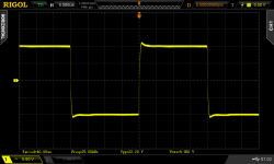
Here are the shots
An externally hosted image should be here but it was not working when we last tested it.
An externally hosted image should be here but it was not working when we last tested it.
As you Can see it is really high frequent... 43MHz so you will not detect it unless you use >60MHz scope
Sonny hi,
Got around to check mine too and when the output passed 38V P-P there it burst out. Could listen to the MOSFETS buzzing along too.😀
The 470pF U2 D to S cap cured it. Thanks.
BTW I still get a bit peaky corners square wave like this one. Its there if lower frequency test signal also. What best compromise method do you possibly recommend to iron it out?
Attachments
For those interrested in a TSSA headphone amp i am preparing an design.
It will be 80x80mm in size, and it will be DC coupled. The extremely low drift makes my 2 stage design a good candidate for an preamp.
Headphone driver module will cost 150€. It will run from +/-15VDC
Hello Sonnya, any update on the progress of the TSSA headphone amp?
- Home
- Vendor's Bazaar
- TSSA V1.7 mosfet Current feedback amp module