It's more like NTC's internal temp peak for 0,7 s at SSA soft start, on outside one can hardly notice a temp rise. 😎
No I'm sorry I didn't try any stabilized power supply for front-end or output at SSA. I had my MonoLith amps with front-end stabilized and regulated but my later designs works fine with just regular general smoothing. I found a lot more sense in separate ciruit sections to have near perfect local DC voltages, currents, etc. I look to general power supply more like as a mains power, enabling low Z, the rest is on certain circuit points.
BTW I sold NC400 monoblocks to one class D fan and he said that they're better than NuForce's monoblocks. 😎
I Don't like supplies with feedback loop, but i always found real improvements with simple ballast (zener at base) for the power stages, even if the previous ones where totally stabilized and regulated.
Why not try-it once, it is not complicated.
Why not try-it once, it is not complicated.
Salas: Thank you for the link. I agree with all positive comment on your photo-journalism. Well done and thank you.
Hi Salas
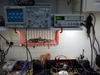
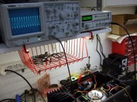
It's nice to see the insight of such beautiful DIY audio session as you thoughtfully prepared it. All predominating factors were measured and evaluated to be sure that everything is electrically OK before starting the test. As expected TSSA (Sonny's version) proved to be competitive enough to play its important role in the presented system. For this thread I choosen four pics as I think they can be very appealing for someone potentially deciding which amp to build.
It's nice to see the insight of such beautiful DIY audio session as you thoughtfully prepared it. All predominating factors were measured and evaluated to be sure that everything is electrically OK before starting the test. As expected TSSA (Sonny's version) proved to be competitive enough to play its important role in the presented system. For this thread I choosen four pics as I think they can be very appealing for someone potentially deciding which amp to build.
Attachments
Last edited:
The MKP caps positions across the feedback electrolytics were tried out and soon abandoned for they introduced some brightness in that system, I may add.
Not surprising.You have good ears ;-)The MKP caps positions across the feedback electrolytics were tried out and soon abandoned for they introduced some brightness in that system, I may add.
.......... they introduced some brightness in that system, I may add.
sounds familiar
try adding 1uF - 4.7uF with 0.2R in series instead - it sounds much better
This has been known among DIYers since a very long time (but rarely discussed here), but unfortunately I have never had the chance to find out if it is true or not (I just prefer to leave out the MKP and choose the best electrolytics) 🙂
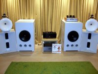
Salas, apart your strange taste for vinyls (nobody's perfect 🙂 your system is a compilation of all what a full life dedicated to audio had bought to me as the best ways to reach the best audio reproduction. Current feedback amps powering circular spherical waves horns, big diameters cones working in their non fractioning range in acoustically treated room.
The photos around-it reveals as well a big part of what life had learned to me as the best to bring joy and happiness: Sea, sun, beautiful landscapes, friends, and music...
You are a lucky guy.
The photos around-it reveals as well a big part of what life had learned to me as the best to bring joy and happiness: Sea, sun, beautiful landscapes, friends, and music...
You are a lucky guy.
That is Vgeorge you picture more likely. Me I am much more of an urban rat with a sonic monkey on my back.😀
This has been known among DIYers since a very long time (but rarely discussed here), but unfortunately I have never had the chance to find out if it is true or not (I just prefer to leave out the MKP and choose the best electrolytics) 🙂
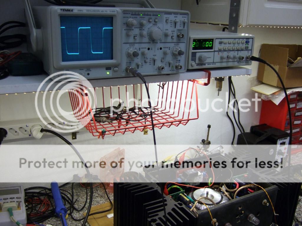
Snubbing can mild out the effect but not eliminate it. If a botch afterthought, especially in a finished amp with short vias that measured 2.5MHZ -3dB, it shall expand the local loop area which is not a good risk. The 200kHz sqW pics are taken with just FC lytics on board everywhere BTW. The lead out negative widening tendency is of scope's performance, had checked that. Just a rebadged Instek 20MHZ value scope for TENMA, but phosphor gives better real time fidelity and noise VS budget DSOs before entering the better pro DSOs price range with higher screen def and update rate market segment.
You can easily measure-it. The combination of the parasitic self of the electrolytic paralleled with the near perfect MKP (or ceramic) produce a resonant circuit. The add of the MKP instead of reducing the impedance at HF, as expected, produce both a peak and an general increase of impedance in a large band at HF. This is true for power filtering as well.This has been known among DIYers since a very long time (but rarely discussed here), but unfortunately I have never had the chance to find out if it is true or not (I just prefer to leave out the MKP and choose the best electrolytics) 🙂
There is 3 solutions to minimize the problem:
-Paralleling little electolytics of the same value to reach the desired values: their parasitic resistances and inductances are individually smaller and they will be divided by the number of paralleled capacitances.
- Paralleling electolytic caps, each time equal or less of 1/10 of the value of the previous one, until you reach the value where the MKP will be 1/10.
- Add a serial resistance to the MKP in order to dump the resonant circuit.
Last edited:
They could be lower THD than unipolar if from same tech exactly so to be apples to apples, still they also fit Jay's phrase "and choose the best electrolytics".
You talk the rails lytics shunt plastics? I talk the feedback lytics shunt plastics.try adding 1uF - 4.7uF with 0.2R in series instead - it sounds much better
Hi guys
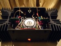
As promised, here's TSSA BIGBT HP.
Credits goes to: Esperado, MiiB, Sonnya, Nico Ras, Salas, Homemodder
Andrej


phenomenal.
For serving the TLP627. : Confused:
You can easily measure-it. The combination of the parasitic self of the electrolytic paralleled with the near perfect MKP (or ceramic) produce a resonant circuit. The add of the MKP instead of reducing the impedance at HF, as expected, produce both a peak and an general increase of impedance in a large band at HF. This is true for power filtering as well.
There is 3 solutions to minimize the problem:
-Paralleling little electolytics of the same value to reach the desired values: their parasitic resistances and inductances are individually smaller and they will be divided by the number of paralleled capacitances.
- Paralleling electolytic caps, each time equal or less of 1/10 of the value of the previous one, until you reach the value where the MKP will be 1/10.
- Add a serial resistance to the MKP in order to dump the resonant circuit.
Alternatively and proactively...I have secured some last resort test to quality tone bypassing. AKA NOS huge Micas.😉

- Home
- Amplifiers
- Solid State
- TSSA - The Simplest Symmetrical Amplifier