Are you sure?The blue led i have ............needs 20mA / 3.5v ........
Have you read the datasheet correctly?
The blue led i have VAOL-3LSBY4 needs 20mA
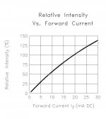
😀 LED is intended to be PS +/-50 V indicator not a room ambient light, which blue LEDs at If=20 mA quickly become.
So 5 mA will be more than enough (see diagram) to do the indicating job properly and certainly we don't want two resistor-heaters on PCB just to feed the indicator LEDs - nonsense. 😉
Attachments


Are you sure?
Have you read the datasheet correctly?
May be not....
😀 LED is intended to be PS +/-50 V indicator not a room ambient light, which blue LEDs at If=20 mA quickly become.
So 5 mA will be more than enough (see diagram) to do the indicating job properly and certainly we don't want two resistor-heaters on PCB just to feed the indicator LEDs - nonsense. 😉
Ok i trust you without any condition... will eliminate the unnecessary resistor
Marc
New progression....
OK nice one 😉
Do you allow some more changes or is it considered as final for you?


OK nice one 😉
Do you allow some more changes or is it considered as final for you?
Ever ready to play....I like the look the board take and the methode to align things
Marc
Note : 0R22 MPC71 and 2N5486/2N5462 are ordered
Last edited:
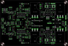
Minor changes, more or less aesthetical ones:
- yes, MUR460 are as big as 2 W resistor, correct size as now
- wire jumpers of correct lenght, aligned to grid with resistors
- 1 mF and 2,2 mF have a little more space around, not all producers have exactly the same diameter for given voltage
- four 15 V zeners move to the side, to have more thicker output track, more current capability
- feedback tracks conducts only mA, so no problem as they are thiner now
- parts alignment to drawn grid lines is now OK
Until now I didn't make any connections check according to sch, that job will be performed when you'll make this final correction. 😉
Regards, Andrej
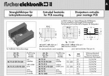
P.S. For VAS 2SA/2SC transistors you can use Fischer heatsinks SK75 37,5 x 32 x 14 mm with two soldering pins for fixation and GND connection 😉
- yes, MUR460 are as big as 2 W resistor, correct size as now
- wire jumpers of correct lenght, aligned to grid with resistors
- 1 mF and 2,2 mF have a little more space around, not all producers have exactly the same diameter for given voltage
- four 15 V zeners move to the side, to have more thicker output track, more current capability
- feedback tracks conducts only mA, so no problem as they are thiner now
- parts alignment to drawn grid lines is now OK
Until now I didn't make any connections check according to sch, that job will be performed when you'll make this final correction. 😉
Regards, Andrej
P.S. For VAS 2SA/2SC transistors you can use Fischer heatsinks SK75 37,5 x 32 x 14 mm with two soldering pins for fixation and GND connection 😉
Attachments
Last edited:
Thanks LC i go on work to evolution. I drawn schematic under eagle and than switch to board. At ths level without any componant placement Eagle present thin yellow line between components pins according connection drawned in schematic. When you done modification in schematic it affect board....Consequence is that normaly there is no mistake in connection if schematic is correct and if parts library are right, but even that i check every time the roting job accordig schematic.
Note : 0R22 MPC71 and 2N5486/2N5462 are ordered
Very good, please also order SK75/37,5 four heatsinks. SK75 has two pins for which at least one has to be connected to the GND. Consider it as a el. part on PCB, give them a room, not to touch their neigbours, cause they will be hot. 😀
P.S. ... and the name is Lazy Cat

Last edited:
Very good, please also order SK75/37,5 four heatsinks. SK75 has two pins for which at least one has to be connected to the GND. Consider it as a el. part on PCB, give them a room, not to touch their neigbours, cause they will be hot. 😀
P.S. ... and the name is Lazy Cat
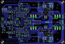
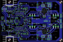
Here it is....KSC/KSA was just at the right place....needed any layout modification were necessary to fit SK75 in.
Marc
PS :"s" gone ....replaced by "z"
Attachments
Here it is....KSC/KSA was just at the right place....needed any layout modification were necessary to fit SK75 in.
Marc
PS :"s" gone ....replaced by "z"
WOW
 , one little sexy PCB, congratulations Marc
WOW
Thanks....was possible only beacause your help....when i see first version, i mesure the road to the final one.
Thanks a lot, yet i must go for bom and purchase. With single side i can easy do it at home on standart PCB board 160x140. Just a "last" advice...: i have on hand 4x 22.000µf 63v screw caps chemi-con U32D. Will that be enough for two channel or should i add 2x10.000 per board or 2x 22.000 U32D per bord for smoothing?
Marc
Nature of the forum is to make things together, faster, in a boost like way. Some designs are successful, some so much that goes to commercial production and sold on ebay by third parties, etc.
4 x 22 mF/63 V is more than enough for two channels at +/-50 V, of course all depends on your's speaker impedance, but for 4 ohm would be OK. I suggest to make the amp as dual mono normally if you have two separate transformers.
The PCB looks really great and I have to inform you that there will be some three resistors more on it, I will draw it and explain why. Don't worry nothing special but now is the time and will give us much easier job later. 😉
4 x 22 mF/63 V is more than enough for two channels at +/-50 V, of course all depends on your's speaker impedance, but for 4 ohm would be OK. I suggest to make the amp as dual mono normally if you have two separate transformers.
I think i have enough transformers (500Va 2x36Vac) for dual mono .... take a look picture under

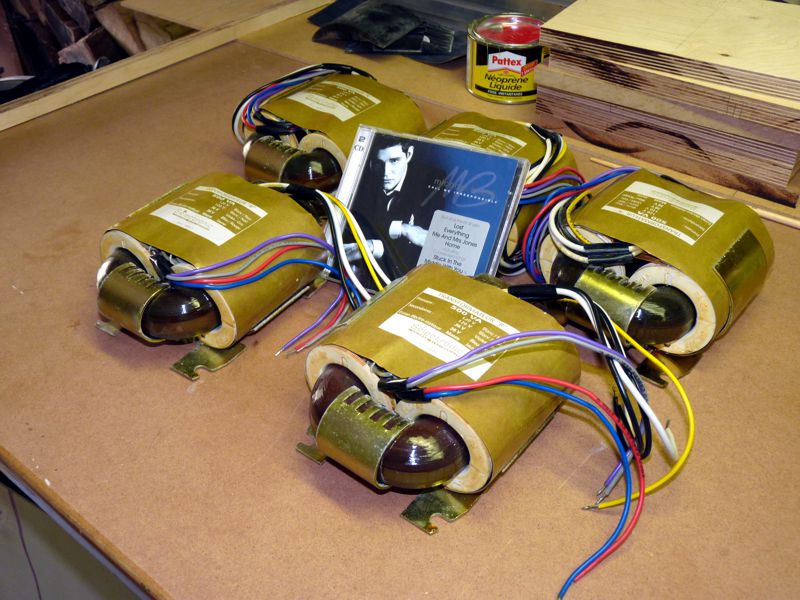
Don't know what futur is made from so i think to had 2x10000µf per board.
The PCB looks really great and I have to inform you that there will be some three resistors more on it, I will draw it and explain why. Don't worry nothing special but now is the time and will give us much easier job later. 😉
I have been waiting for modification
Marc
Why you put that remote ''on'' thing? Is it for home theater installations? And how can we skip it locally on board? Maybe better include a 3 way small switch that provides +12V (on), 0V (mute), remote, positions?
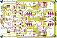
This update enables TSSA BIGBT HP to be even more universal:
- serial diode MUR160 plus 22 ohm resistor in power supply rails helps to improve PSRR
- +/-OPT pins enables to connect separate power supply for the front-end (MUR160 and 22 ohm are omitted)
- power supply LED indicators for both front-end and output stage are present
- serial compensating resistor added to NTC (serves to calibrate NTC thermal response)
- serial resistors added to SK75 heatsink's GND connection (serial RC filter)
- 1 uF/63V decoupling capacitors added close to VAS transistors supply rails
- TLP627 input now accepts 12 V remote signal (serial resistor added)
- LT1034 replaced by TL431
- R2-R9 values stated for +/-50 V power supply rails
And that's about it. 😉
Attachments

Last edited:
Why you put that remote ''on'' thing? Is it for home theater installations? And how can we skip it locally on board? Maybe better include a 3 way small switch that provides +12V (on), 0V (mute), remote, positions?
Hi Salas 😉
No, TLP627 serves to switch output transistors on/off, practically replaces an output relay. 😉
- Home
- Amplifiers
- Solid State
- TSSA - The Simplest Symmetrical Amplifier