Idefixes, if you have thermal tracks than first make point to point wire nest. Mount TT-s on a heatsink, than step by step add and wire parts, similar like sonnya did. I think it is not very demanding job to do and test, before you go to PCB. You will also check if everything is OK and if the sound is acceptable. 😉
And don't forget to thermally couple input pair. 🙂
And don't forget to thermally couple input pair. 🙂
Last edited:
Idefixes, if you have thermal tracks than first make point to point wire nest. Mount TT-s on a heatsink, than step by step add and wire parts, similar like sonnya did. I think it is not very demanding job to and test, before you go to PCB. You will also check if everything is OK and if it's sounds acceptable.
I am not aware with point to point.....and find funny pcb art work as i can produce at home... I have 5 couple of NJL1302DG/NJL3281DG on hand , 47.000µ 35V and a 400va 2x18V toroid transformer i can swap just for test from a another project
It is an ideal opportunity to try with P2P, sch is simple, diodes are integrated, so really low parts count. You will also learn how good P2P is, it will hardly be beaten with any PCB. 😀
They are fine, if you can measure hFE, it should be max. let's say 500+
Pinout is different to BC's. It will be very nice to see another wire nest, just go for it and please don't forget to take pics. 😀
Pinout is different to BC's. It will be very nice to see another wire nest, just go for it and please don't forget to take pics. 😀


Good lord that looks intimidating. It would take me a month just to do the pcb. Might try anyway after the simple tssa.


 Andrej
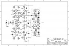
I agree sonnya 😉
Any more suggestions? As that would brings us to an optimal consensus version. 😎
Any more suggestions? As that would brings us to an optimal consensus version. 😎

Hi, LC could adapte the TSSA HP for +/-50Vdc? It would be really nice from you.
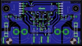
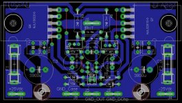
For fun il will try the liitle pcb for TSSA TT.
Marc
For fun il will try the liitle pcb for TSSA TT.
Marc
Testing/ironing out TSSA BIGBT, allowing/confirming a range of PSUS 45V-70V and issuing a board would be a happy practical conclusion of the Andrej ideas threads. What is the projected power range for those supply voltages?
In TSSA I will use these two BIGBT output beauties.
At low power category the SSA will face a very tight competition with other class-A amps. And especially the BIGBT output may not be suitable for this kind of competition. But at high power category (class-AB) the SSA may become a winner.
the simplest !
post71 shows ~75 components.
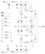
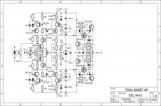
This one is HP-high performance version, based on TSSA, logically that it has more components, performing specialized jobs. 😀
The only one named the simplest-TSSA from post #1 has 17 parts all together, successfully tested by sonnya. 🙂
Exact essence of this and SSA thread lies in Salas words:
Testing/ironing out TSSA BIGBT, allowing/confirming a range of PSUS 45V-70V and issuing a board would be a happy practical conclusion of the Andrej ideas threads.
All varieties of the SSA circuit has the purpose of thread evolution and maybe, I say maybe, from all the posts we'll squeeze out only one little diamond. 😉
Hi LC, what is the +/-Vdc rail limit to use with #57 schématic?
Marc
Definitive limiting factors are BC550/560 Uce max. and their power dissipation. Power transistors can take into/from their bases 100 mA and more, and that can be well over BC's capabilities especially if you consider SOAR. BC's can be replaced with 2SA/SC TO-126 transistors but with a little decrease in HF and noise performance. These four BJT-s are major limiting factor, also with only one output pair you can not expect to get out more than 50 Wrms/4 ohm load by any BJT selection. Please try by yourself to calculate BC's dissipation in the worst case conditions and you will see.
Lateral mosfet version has a little more headroom, but charging gate input capacitance at HF is another difficult task. Still no more than 50 W/4 ohm full power bandwidth . 😉
Last edited:
- Home
- Amplifiers
- Solid State
- TSSA - The Simplest Symmetrical Amplifier