Check out Designing a PSU with DuncanAmps PSUD II by DHTROB, which explains his power supply design process using PSUD2. I thought it might illustrate how to use PSUD2 to diagnose PSU startup and resonance behaviors,

I am a fan of inserting series 1N4007 diodes with tube rectifier anodes, and imho it's well worth making the effort to avoid one likely failure mechanism (and subsequent collateral damage) as the tube ages, especially as very few have the ability to maintenance check the leakage resistance at PIV of their rectifier valves and so may let them continue to operate as they continue to degrade.
What type of resistor are you using for R5? That's the first resistor in series with the rectifier diodes for the negative supply, correct?
If so, it could be that on startup there's a lot of voltage differential across R5, and it's burning out after a few power cycles. Try using a 2W or 3W resistor rated for much higher voltage than it will ever see. 1/2 watt metal film resistors have a max voltage rating of 300V or 350V. It could be that you need to use bigger wattage resistors for their larger voltage ratings.
This Vishay 270R 3W metal film resistor is rated for 750V.
https://www.newark.com/vishay/pr03000202700jac00/metal-film-resistor-270-ohm-3/dp/94C3772
That would remove this worry, right?
Thank you! George just gave me the same advice.
I don’t know how likely this is with the new resistors, but let’s not find out.
I had a 1W Vishay there, I’ll upgrade to 3W.
My terminal blocks are going to wear down if I don’t manage to keep that board in there. 😂
I am a fan of inserting series 1N4007 diodes with tube rectifier anodes, and imho it's well worth making the effort to avoid one likely failure mechanism (and subsequent collateral damage) as the tube ages, especially as very few have the ability to maintenance check the leakage resistance at PIV of their rectifier valves and so may let them continue to operate as they continue to degrade.
Not compatible with that amp.
Check out Designing a PSU with DuncanAmps PSUD II by DHTROB, which explains his power supply design process using PSUD2. I thought it might illustrate how to use PSUD2 to diagnose PSU startup and resonance behaviors,
I used it and it tells me everything will be fine, but I cannot show it the negative bias supply load.
Refer to my comment in post #54.
Ah yes I recall now. Cutting traces. Probably isolating B- from B+ to make it work.
That being said, I want to try to make it work as it was designed, provided it’s just a matter of upgrading a few parts.
Thank you for the suggestion, though.
Check out Designing a PSU with DuncanAmps PSUD II by DHTROB, which explains his power supply design process using PSUD2. I thought it might illustrate how to use PSUD2 to diagnose PSU startup and resonance behaviors,
Great guide!
@6A3sUMMER @rongon @TonyTecson @trobbins
You guys have already given such a great amount of knowledge on this topic, I thought I would follow up and report in, as I promised actually.
Let's start with the PSUD2 data:


This simulation is with the 2 65 ohm/20W resistor in series with each tap of the HV secondary.
Since I decided to take the board out one more time to upgrade R5 to a 3W part, I decided to also to measure:
1) The unloaded voltage output of the HV winding, (679VAC, very good regulation on that PT!)
2) The DCR of the HV between both ends (202.5 ohm)
Then I made an estimate of the ESR of the first capacitor based on the datasheet listing 0.2 as tan δ (MAX.).
And I looked up the ESR of the second capacitor; it's listed as 570 mOhm.
Finally, I set the load as a 150 mA current sink.
I got the results shown above.
2 remarks:
1) According to the software, C1 never sees more than 406.46V. So the current cap rated at 450VDC would be sufficient.
2) The smoothing works very well.
So, what do you think? Should I still replace these caps with 500VDC parts?
You guys have already given such a great amount of knowledge on this topic, I thought I would follow up and report in, as I promised actually.
Let's start with the PSUD2 data:
This simulation is with the 2 65 ohm/20W resistor in series with each tap of the HV secondary.
Since I decided to take the board out one more time to upgrade R5 to a 3W part, I decided to also to measure:
1) The unloaded voltage output of the HV winding, (679VAC, very good regulation on that PT!)
2) The DCR of the HV between both ends (202.5 ohm)
Then I made an estimate of the ESR of the first capacitor based on the datasheet listing 0.2 as tan δ (MAX.).
And I looked up the ESR of the second capacitor; it's listed as 570 mOhm.
Finally, I set the load as a 150 mA current sink.
I got the results shown above.
2 remarks:
1) According to the software, C1 never sees more than 406.46V. So the current cap rated at 450VDC would be sufficient.
2) The smoothing works very well.
So, what do you think? Should I still replace these caps with 500VDC parts?
Also, side note, here is a picture of the R5 that failed open:

It looks beautiful. 😂
All of my previous failed resistors looked gored…when I could find them pieces. 🤣
It looks beautiful. 😂
All of my previous failed resistors looked gored…when I could find them pieces. 🤣
I'll maybe answer my own question...
Here is the simulation if I replace the 150 mA current sink with a 150kOhm (the value of R30 in the TSE-II schematic) resistive load:

Based on that simulation, I should definitely replace C4, C5 and C15 with 500VDC parts.
Here is the simulation if I replace the 150 mA current sink with a 150kOhm (the value of R30 in the TSE-II schematic) resistive load:
Based on that simulation, I should definitely replace C4, C5 and C15 with 500VDC parts.
Yes some care in what load is used is needed when interpreting a simulation plot. For example, if the rectifier 'turns on' well before the amp's valves start conducting then your sim with 150k load is representative of the initial voltage on the B+ rail, which may exist for seconds (eg. if the rectifier was ss or directly heated). That is also an outcome if valves are not working or removed for servicing.
If an indirectly heated rectifier is used then the load on B+ could be increasing as the B+ rail is rising whilst the rectifier diodes start to increase their conduction.
And the other main scenario to consider is a 'hot start' where load resistance is directly applied and diodes start conducting immediately.
PSUD2 can't accurately sim the dynamic portion of those scenarios using just a resistive load, or constant current load, or some soft start characteristic. In general, I prefer to use a resistive load that achieves a 150mA current (ie. circa 2k7), and no soft start, to identify a hot start scenario, rather than use a 150mA constant current loading.
Some other subtleties (eg. inductor model) of PSUD2 simulation are described in the following link https://dalmura.com.au/static/Valve amp fusing.pdf.
With respect to e-cap voltage rating and turn-on surge, there is some discussion in section 6 of the following link https://dalmura.com.au/static/Power supply issues for tube amps.pdf which may suggest you are ok with 450V rated e-caps.
Ciao, Tim
With respect to e-cap voltage rating and turn-on surge, there is some discussion in section 6 of the following link https://dalmura.com.au/static/Power supply issues for tube amps.pdf which may suggest you are ok with 450V rated e-caps.
This PDF is absolutely amazing. Thank you for sharing!
yes, they fail as opens, i use 5 watts metal films, in my case the metal film smokes, i turned power off, but after it has cooled down, i measure the resistance and it still as a labeled, of course a blackened resistor is not a good sight to see..Also, side note, here is a picture of the R5 that failed open:
View attachment 1195908
It looks beautiful. 😂
All of my previous failed resistors looked gored…when I could find them pieces. 🤣
but i still can use them in experiments..
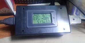
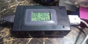
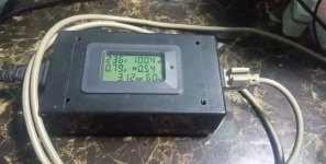
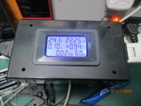
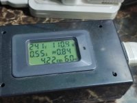
i never used PSUDII simulators, i use power monitors instead to see what is happening in the circuit real time..
when the switch is flicked, there is an inrush, a second or two later, it goes down, the current i mean, and then as the filaments come up, you can see the power going up till it settles to a final value...
it takes a minute or two for things to get stabilized to a final value...
https://www.lazada.com.ph/products/pzem-022-100a-6in1-digital-ac-80260v-power-energy-monitor-voltage-current-kwh-watt-meter-i3895507375-s20862826629.html?c=&channelLpJumpArgs=&clickTrackInfo=query%3Apower%2Bmonitor%3Bnid%3A3895507375%3Bsrc%3ALazadaMainSrp%3Brn%3Aa0944136719bf13eeb951f50d29cdc3b%3Bregion%3Aph%3Bsku%3A3895507375_PH%3Bprice%3A699%3Bclient%3Adesktop%3Bsupplier_id%3A500254662204%3Bpromotion_biz%3A%3Basc_category_id%3A22652%3Bitem_id%3A3895507375%3Bsku_id%3A20862826629%3Bshop_id%3A3808826&fastshipping=0&freeshipping=0&fs_ab=2&fuse_fs=&lang=en&location=Bataan&price=699&priceCompare=&ratingscore=5.0&request_id=a0944136719bf13eeb951f50d29cdc3b&review=1&sale=4&search=1&source=search&spm=a2o4l.searchlist.list.i40.7cd66352IIXXKx&stock=1
Attachments
-
 6ff82f03-8dee-49cf-8dc0-39bde5a8eb04photo.jpeg395.4 KB · Views: 47
 -
 19323-53dc3be19bff27d001b1c6a5945d3dec.jpg150.9 KB · Views: 54
 -
 393012ae-a801-4f46-83fe-2134e6b45ccfphoto.jpeg353.1 KB · Views: 49
 -
 314393969_505724024808941_6671635513231241952_n.jpg339.9 KB · Views: 45
 -
 IMG_2062.JPG404.3 KB · Views: 52
 -
 IMG_20221226_173003.jpg471.2 KB · Views: 46
Last edited:
the way i design my psu is to know what tubes, tabulate their filaments, what type amplifier and bias operating points..
selecting the suitable power transformer comes next...
That’s the best way to go, no doubt.
@6A3sUMMER @rongon @TonyTecson @trobbins
You guys have already given such a great amount of knowledge on this topic, I thought I would follow up and report in, as I promised actually.
Let's start with the PSUD2 data:
View attachment 1195905
View attachment 1195906
This simulation is with the 2 65 ohm/20W resistor in series with each tap of the HV secondary.
Since I decided to take the board out one more time to upgrade R5 to a 3W part, I decided to also to measure:
1) The unloaded voltage output of the HV winding, (679VAC, very good regulation on that PT!)
2) The DCR of the HV between both ends (202.5 ohm)
Then I made an estimate of the ESR of the first capacitor based on the datasheet listing 0.2 as tan δ (MAX.).
And I looked up the ESR of the second capacitor; it's listed as 570 mOhm.
Finally, I set the load as a 150 mA current sink.
I got the results shown above.
2 remarks:
1) According to the software, C1 never sees more than 406.46V. So the current cap rated at 450VDC would be sufficient.
2) The smoothing works very well.
So, what do you think? Should I still replace these caps with 500VDC parts?
The ringing (overshoot, undershoot) at power-up might be worrisome. You can test in simulation using a stepped current load in PSUD2, which can be informative. You can see if the power supply is likely to oscillate with quick changes in current draw, such as when a program peak clips the amp into blocking or grid current.
Set I1 to be a multi-stepped current source (stepped load) with a delay of perhaps 1 or 2 seconds between initial current draw and second current draw. SY posted about this way back in 2008... https://www.diyaudio.com/community/threads/psud-2-road-guide.115260/#post-1401641
I'd set the initial current draw to be about 25mA and then the second current draw to the full 150mA. You want to see if the power supply rings when hit with a big step in current draw.
This test was also described in Morgan Jones "Valve Amplifiers 3rd Edition" and is also in the 4th edition.
I'd set the initial current draw to be about 25mA and then the second current draw to the full 150mA. You want to see if the power supply rings when hit with a big step in current draw.
Stepped current sink, 25mA to start 150 mA after 2 seconds.
No "soft-start" enabled.
The more I think about this, the more I wonder if it is meaningful to the TSE-II at all.
First, PSUD2 doesn't see the B- supply.
Second, the 5AR4 takes a good 10 seconds to conduct. By then, the 2 5842s and the 2 300Bs filaments have had plenty of time to warm up and as B+ ramps up slowly, they start drawing current to the level of their bias point.
Hence, there is no sudden 100 mA jump in load at any point in time.
But I guess this test is solely to assess the odds of oscillation and ringing.
Last edited:
- Home
- Amplifiers
- Tubes / Valves
- TSE-II build and arcing rectifiers (mostly 5AR4 vacuum tubes, new issue)