At the request of those who are helping me with this issue, and for the benefit of all members of the community who may someday experience a similar problem, I am going to gather the details of this "case" in this new thread...
The circuit in question is the TSE-II SE amplifier with 5842 input tubes and 300B power tubes.
The schematic is attached to this post.
The power transformer in this case is:
https://edcorusa.com/products/xpwr178-660v330-0-330-200ma-6-3v3-15-0-3-15-6a-5v2-5-0-2-5-3a
I measured DCR as follows:
I did use this choke in place of R4:
https://edcorusa.com/products/cxc125-10h-200ma-10h-200ma-choke
Its DCR is 75 ohm (vs. the 150 ohm R4).
C4 is a quality 47uF 450V electrolytic capacitor.
(A 5AR4 should be able to handle a 60uF input capacitor, according to the datasheet.)
C5 is a quality 150uF 450V electrolytic capacitor.
I have the following motor run capacitor in parallel with C5:
https://www.digikey.com/en/products/detail/kemet/C870CG36100AA0J/6556371
(100 uF Film Capacitor 470V Polypropylene)
The circuit in question is the TSE-II SE amplifier with 5842 input tubes and 300B power tubes.
The schematic is attached to this post.
The power transformer in this case is:
https://edcorusa.com/products/xpwr178-660v330-0-330-200ma-6-3v3-15-0-3-15-6a-5v2-5-0-2-5-3a
I measured DCR as follows:
- Primary winding: 1.75 ohm
- HV secondary: 35.3 ohm and 36.8 ohm
I did use this choke in place of R4:
https://edcorusa.com/products/cxc125-10h-200ma-10h-200ma-choke
Its DCR is 75 ohm (vs. the 150 ohm R4).
C4 is a quality 47uF 450V electrolytic capacitor.
(A 5AR4 should be able to handle a 60uF input capacitor, according to the datasheet.)
C5 is a quality 150uF 450V electrolytic capacitor.
I have the following motor run capacitor in parallel with C5:
https://www.digikey.com/en/products/detail/kemet/C870CG36100AA0J/6556371
(100 uF Film Capacitor 470V Polypropylene)
Attachments
The story continues...
I have had problems with 3 rectifier vacuum tubes: Sovtek 5AR4, a Linlai 5U4G and most recently a Psvane 5AR4. All new issue units. The Sovtek flash during the first few hours. The Linlai I don't recall. The Psvane lasted 4-5 months.
@Francois G first helped me with this post:
And then this post:
@6A3sUMMER gave me this advice:
I have had problems with 3 rectifier vacuum tubes: Sovtek 5AR4, a Linlai 5U4G and most recently a Psvane 5AR4. All new issue units. The Sovtek flash during the first few hours. The Linlai I don't recall. The Psvane lasted 4-5 months.
@Francois G first helped me with this post:
JJ’s 5AR4s have been accused of fragility, but many cases of arcing JJ 5AR4s were caused by insufficient resistance in the secondary winding of modern power transformers. (Check a detailed data sheet for the specs on the resistance 5AR4 requires between the anodes.)
More information about your amp would be helpful to identify potential problem areas. Specifically, are you using a choke in place of R4?
And then this post:
The 5AR4 is more important for the startup sequence than “preventing cathode stripping”. The 300b bias has to be up and stable by the time B+ rises to the max value.
I don’t know what operating conditions you are aiming for for the 300b outputs. If you could stand to loose a few volts my preference would be to keep the 5AR4 but use inrush current limiters and/or resistors in the PT secondary (or center tap), not adding resistance to the choke (to keep the B+supply as low impedance as possible). I expect if you have sufficient resistance (according to the data sheet) in the 5AR4 anode circuit you will not experience further arcing.
Let us know how this works out. Good luck!
@6A3sUMMER gave me this advice:
A few comments:
A 120 to 330-0-330 transformer "multiplies" the primary DCR x 3 (the step up ratio).
If the primary DCR = 15 Ohms, then it "Adds" 3 x 15 Ohms in series with each 330V lead
(adds 45 Ohms in series with the secondary DCR of each 330V lead).
A good question to ask is the B+ filter using a cap input filter (rectifier cathode directly connected to the first B+ cap)?
How many uF is that capacitor?
What is the maximum capacitor rating for the 5AR4, versus the cap you are using?
Is the maximum plate voltage of the 5AR4 exceeded (the max rating for a capacitor input B+ filter)?
I have seen the 5AR4 arc. It usually indicates one of three things:
Too many uF first filter cap
Plate voltage too high for cap input filter
Poor quality 5AR4, some have un-even cathode coating, and have a Bump in the coating that is closer to the plate(s).
The only time I have worked on equipment that uses an inrush limiter to the solid state rectifiers (directly from the power mains), and that directly drove 750uF capacitors (no power transformer).
That requires such a device to limit the inrush current.
Other than that kind of circuit, I am not a fan of that 'solution'.
The story continues...
I put the amplifier on the bench and I am trying to figure out the best course of action to keep rectifier tubes alive longer. 😉
The input capacitor, at 47 uF, should be OK, since a 5AR4 is meant to work with up to 60 uF.
The 5AR4 datasheet gives:

So, I am guessing 330V RMS at either plates should not be a problem.
What is clear, however, is that I should have at least 90 ohm of limiting resistor at each plate, and I do not, since the DCR of my HV winding is ~35 ohm and the reflected impedance of the primary would not fill the gap between 35 ohm and 90 ohm.
I put the amplifier on the bench and I am trying to figure out the best course of action to keep rectifier tubes alive longer. 😉
The input capacitor, at 47 uF, should be OK, since a 5AR4 is meant to work with up to 60 uF.
The 5AR4 datasheet gives:
So, I am guessing 330V RMS at either plates should not be a problem.
What is clear, however, is that I should have at least 90 ohm of limiting resistor at each plate, and I do not, since the DCR of my HV winding is ~35 ohm and the reflected impedance of the primary would not fill the gap between 35 ohm and 90 ohm.
The story continues...
Finally, here comes the part where "solutions" are considered...
I see 5 possibilities:
1) Adding power resistors in series between each tap of the HV winding and the rectifier plates. 55 ohm should do. It would be wasted energy, but it would keep the 5AR4 happy, if the datasheet is to be believed. It would also drop some B+, which I may not want.
2) Adding a CL-90 thermistor on the primary winding, and that would probably let inrush currents pass without tickling the rectifier the wrong way. @6A3sUMMER explained he is not a fan of that "solution".
3) Adding a CL-140 thermistor in series with the HV winding CT. I don't know anything about that solution.
4) Adding silicon diodes in series with the plates.
5) Replacing the tube rectifier with a device made of 2 silicon diodes and a thermistor. (Weber WS1T) @Francois G is not a fan of that solution, as it eliminates the nice slow start provided by the 5AR4 rectifier.
If it did the job, I would lean towards "2)" as it seems to be the simplest "brew" to drink.
Ouf!
I am sorry for the long-winded monologue.
I have not decided which way I will go yet.
If anyone else has dealt with a similar issue before, please reply. I am sure there is more I could learn about this before I sacrifice another 5AR4. 🙂
I am sorry for the long-winded monologue.
I have not decided which way I will go yet.
If anyone else has dealt with a similar issue before, please reply. I am sure there is more I could learn about this before I sacrifice another 5AR4. 🙂
i have stopped using secondary's with center taps for tube rectifications a long time ago, i use hybrid types, a single ht secondary...you can add series resistors to limit inrush in the case of cap input dc supply...chart below gives the formula...
Attachments
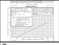

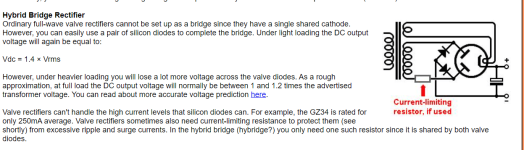
since i design and build all transformers used in my builds i m happy to use FWB or full wave doublers instead...more information here: https://www.valvewizard.co.uk/bridge.html
by using the hybrid type, arc overs can be minimized if not altogether avoided sins the tribe rectifier will never see the kind of ac inputs that the full-wave center tapped arrangements have, tube stress is mitigated..
by using the hybrid type, arc overs can be minimized if not altogether avoided sins the tribe rectifier will never see the kind of ac inputs that the full-wave center tapped arrangements have, tube stress is mitigated..
Attachments
i have stopped using secondary's with center taps for tube rectifications a long time ago, i use hybrid types, a single ht secondary...you can add series resistors to limit inrush in the case of cap input dc supply...chart below gives the formula...
So, that’s 1 more vote for series resistors!
3) Adding a CL-140 thermistor in series with the HV winding CT. I don't know anything about that solution.
This one is my favorite now, as it would not impact other secondary windings. 🥸
The CL-90 on the primary winding would impact all secondaries.
Now, there’s the issue that 330V exceeds the voltage rating of a CL-140. Although, the datasheet doesn’t specify a max voltage rating.
https://www.mouser.com/datasheet/2/...mometrics_NTC_Inrush_031814_web_p-1315885.pdf
Last edited:
Why not just do that. No more arcing 5AR4's. Cheap too! 🙂4) Adding silicon diodes in series with the plates.
jeff
Why not just do that. No more arcing 5AR4's. Cheap too! 🙂
jeff
I agree. I can solder one end to the transformer wire and shove the other into the PCB terminal block. Oops, that sounds bad. I would put a piece of wire on the other side too. 🤣
Purists will hunt me down and say I am diluting the magic properties of tube rectification.
But I’m sure I can live with that.
If the loaded primary is 330VAC, then the peak voltage is 1.4 x 330V = 462V peak.
Use 500V caps there; if the output tubes do not load the power supply, then the 5AR4 rectifier voltage drop is far less, and the secondary puts out more than 330VAC.
Tube rectification?
I gave that up for solid state rectifiers that connect to Choke Input filters.
One power supply uses HEXFREDs, a little expensive, but no more expensive than a very good tube rectifier, and no 5V winding needed.
Your choice may vary
Last edited:
Use 500V caps there; if the output tubes do not load the power supply, then the 5AR4 rectifier voltage drop is far less.
Good point. Thank you.
what could be simpler than a single secondary winding to feed 5ar4 rectifier plates and add to 1n4007's to complete?I agree. I can solder one end to the transformer wire and shove the other into the PCB terminal block. Oops, that sounds bad. I would put a piece of wire on the other side too. 🤣
Purists will hunt me down and say I am diluting the magic properties of tube rectification.
But I’m sure I can live with that.
with FWCT psu, half the time or every 180 degrees of the electrical cycle, that half of the winding is not delivering currents, waste of electrical cycles....
transformer utilization is greater by about 30% more so lesser heating of the cores...
purist do what purists do, miss out on the good things...
Last edited:
i choose psu ecaps on the basis of all but the rectifier tube plugged in, what is the resulting B+? will it exceed the wvdc of the ecap?Good point. Thank you.
a rule of thumb I observe, 80% ecap's wvdc, working volts dc spec for safety...
yess.....Why not just do that. No more arcing 5AR4's. Cheap too! 🙂
jeff
i choose psu ecaps on the basis of all but the rectifier tube plugged in, what is the resulting B+? will it exceed the wvdc of the ecap?
a rule of thumb I observe, 80% ecap's wvdc, working volts dc spec for safety...
B+ will not exceed the 450V rating of the ecaps, in fact it won’t exceed 400V.
But I think @6A3sUMMER is trying to cover the brief power-on period where things could get close.
it is written down on the tube datasheet all along, just follow it and you are home free.....So, that’s 1 more vote for series resistors!
using the higher rating ecap that you have is never wrong...B+ will not exceed the 450V rating of the ecaps, in fact it won’t exceed 400V.
But I think @6A3sUMMER is trying to cover the brief power-on period where things could get close.
- Home
- Amplifiers
- Tubes / Valves
- TSE-II build and arcing rectifiers (mostly 5AR4 vacuum tubes, new issue)