Hello,
Newbie posting please be gentle.
Can anyone give direction to troubleshoot my Philips Valve Radio. This radio is around 50 years old. 4/5 years a go I played it and it was working. However at that time I checked only for 3/4 mins. and stored it away.
Two years back I played it again to play 78rpm Shellac with pickup input. It played for approx. 5 mins. Then there was little burst sound inside the radio. Speaker went silent. So I thought some capacitor must have been blown. I stored it away again.
Now during lockdown I have time so I opened back cover. Most capacitors visually looked OK. So I plugged it in. A little burning smell and light plume of smoke came from area which has high power resistor R15. (Shown in Red Dot in attached pic.) I noticed a tiny sparking in Rectifier tube. I immediately shut it off. Within this 3/4 seconds of power ON the resistor R15 was exteremenly hot and I also noticed original 1.5K is replaced with 1K. To check further around this area to see if there is any short and drawing current, I checked (Green Dots) capacitors C34, C35, C38 & C37 with Capacitance Meter and Resistor R20. They seem OK. C34/C35 are 32uF+32uF dual capacitor in single case, one part of which is replaced with 50uf cap long time back.
I have removed the radio from wooden chassis and can take pictures of area from where little smoke came.
Kindly suggest what to do ?
1) Is R15 resistor of 1K the culprit ?
2) Could Valve Rectifier be damaged and making Resitor too hot ?
3) Anything else to check ?
Thanks very much.
Attachments

Hi Hiten!
I think you may get a better response if this topic were to be transferred to the 'Amplifiers - Tubes/Valves' section.
I think you may get a better response if this topic were to be transferred to the 'Amplifiers - Tubes/Valves' section.
I would double check that the line voltage selector is at 230V. Then I would verify that the loudspeaker coil is not open. I would also check all windings of output transformer for continuity.
I would make R15 1.5k. I would check and measure all resistors around ECL82.
If R15 still gets very hot, I would temporary remove ECL82.
If R15 then works OK, I would suspect ECL82 malfunctions and I would find a replacement.
Check all above and report back. (If you remove ECL82, DC voltages across C34, C35 will increase a bit but not much)
George
Electrolytic capacitor leakage currents can become excessive when they have hardly been used for very long, the coupling capacitors of the last audio valve can leak (especially paper caps) and occasionally a valve may get grid emission problems.
After the line voltage selector check, try very slowly charging C34 and C35 to their nominal voltage and keeping them there for an hour before doing anything else. One way to do that is to remove B3, disconnect C34's positive terminal from everything except R15 and inserting a 100 kohm resistor between B5 and C35. This should bring their leakage back to normal values.
After discharging them again, connect everything normally, but don't place back B3. Turn on the radio while measuring the voltage at pin 3 of B3's holder. Its DC level should be and stay within a few hundreds of millivolts from 0 V. If it becomes much higher, there must be a leaking capacitor. Paper capacitors are notorious in this respect.
If everything goes well, put back B3 and again turn on the radio while measuring the DC at its pin 3. It should again be within a few hundred millivolts from 0 V. If not, turn off the radio and try a new valve for B3.
You'll need to replace all of the electrolytics and the film or paper coupling caps. Avoid messing with the RF section.
It's a terrible idea to plug any tube radio or amplifier directly into the mains after it has sat for years, and particularly after it went into the closet after a major malfunction.. 🙂
Read up on HV safety practice and the newbie thread in tubes & valves.
You should trouble shoot with a "dim bulb" (search here) in series with the AC to the radio to limit current in the event of a fault so you don't smoke irreplaceable parts.
You'll need to replace all of the electrolytics and the film or paper coupling caps. Avoid messing with the RF section.
...and with the IF tuned circuits.
It really depends on whether you want to retain as many as possible of the historic components. The electrolytics are often just fine after slowly charging the supply filter capacitors to regenerate the oxide, although they may also be dried out. Paper capacitors are almost always leaky, but there are only a few places where that can cause damage. As far as I know, there are usually no problems with plastic film capacitors.
thanks Everyone.
Thanks Galu. I request mods to please move this thread.
Gpapag, there is no voltage selector. This is made in India so doesn't have any. I will replace 1k high watt resistor with 1.5K once our Lockdown is lifted. I removed the speaker and checked output transformer secondary it shows 4.5 ohms. I checked speaker coil it is around 11 ohms and plays music with other small amplifier. The measured resistors with ECL82 valve removed. They are R13 (11.4M), R14 (360 ohms), R16 (238 ohms) R17 (3.36 K) which are within tolerance of specified values.
MarcelvdG, I measured the two capacitors C34 and C35 with capacitance meter they are 27uf and 37 uf which is specified in the schematic. I will do slow recharging. the radio is removed from wood cabinet. and valve and speakers need to be put back again.
Kevinkr, Yes I should not have hurried. But before plugging it in I visually checked all capacitors there was no burst cap so turned it on. The C34 and C35 are measuring well but to be on safer side I do plan to replace them once our Lockdown is lifted (In a week or so). I can make series bulb tester. Will take necessary precaution.
I am little worried about ferrite rod antenna with thin coils. Need to safeguard it. So making some temporary arrangement to keep it protected while moving/turning chassis while testing.
I also have extra valve/tubes as backup.(But they are in my office). Prices of vintage parts are exhorbitant so hesitant to replace valves and check unless the fault is found.
anything else need to be checked ?
...and with the IF tuned circuits.
It really depends on whether you want to retain as many as possible of the historic components. The electrolytics are often just fine after slowly charging the supply filter capacitors to regenerate the oxide, although they may also be dried out. Paper capacitors are almost always leaky, but there are only a few places where that can cause damage. As far as I know, there are usually no problems with plastic film capacitors.
MarcelvdG,
I understand people for historic authenticity retain old parts. This Radio was bought by my dad in early 70s. So want to keep it in running condition. And yes capacitors are measuring 27uf and 37uf. Original are specified as 32uf. I wouldnt mind replacing them with new one and check once our lockdown is lifted as I dont know how much old capacitors will last.
I visually checked almost all components it doesn't seem to have paper capacitors. And no capacitors seem to have burst. Unless it is hidden at bottom of the various components and wires. Some capacitors are also strange bulby clay like with color bands and look ok.
regards
Last edited:
gpapag,
I checked Primary of output transformer. There are three terminals and coils are marked S17 and S18 (see schematic) S18 is 27 ohms and S17 shows open. S17 has parallel capacitor to it which I have not removed. s17 should show some resistance isn't it ?
regards
I checked Primary of output transformer. There are three terminals and coils are marked S17 and S18 (see schematic) S18 is 27 ohms and S17 shows open. S17 has parallel capacitor to it which I have not removed. s17 should show some resistance isn't it ?
regards
That's peculiar. When S17 is open, there should be no or practically no sound coming out of the loudspeaker, but it can't cause damage to R15.
MarcelvdG,
as mentioned earlier I checked speaker separately with another amplifier. It was not connected to radio circuit. When it was in the radio circuit connected the little burst sound came and speaker went silent as said in first post. Also R15 is not damaged it gets very very hot within 3/4 seconds
as mentioned earlier I checked speaker separately with another amplifier. It was not connected to radio circuit. When it was in the radio circuit connected the little burst sound came and speaker went silent as said in first post. Also R15 is not damaged it gets very very hot within 3/4 seconds
Last edited:
OK, so you have a damaged output transformer and some other defect that causes R15 to get hot, which may just be a power supply electrolytic capacitor of which the oxide needs to be reformed. What caused the output transformer to break down is unclear, but it could be something that caused the output pentode to draw too much current, like a leaky coupling capacitor or grid emission.
Here in the Netherlands, the quarterly fairs of the NVHR (last one cancelled because of corona), Radio Twenthe in the Hague ( home - Radio Twenthe ) and the Dutch valve radio forum Nederlands Forum over Oude Radio's are three possible sources for a replacement transformer. I don't know any in India. You could use a transformer meant for a single-ended valve amplifier as well.
If you should manage to repair or replace the transformer, please use the dim bulb tester Kevin recommended to reduce the risk of blowing it up again.
A makeshift solution would be to replace S17 with S18 and S18 with a short; this will result in less volume and more hum, but at least it should produce some sound then. Please use the dim bulb tester if you should try this.
As Marcel wrote, a leaky coupling capacitor is 90% the root cause of the burned transformer. Check C36, then C32. The ECL82 may have died too.
If it is not potted, it is possible to unwind the output transformer and rewind it by hand. I’ve done it a few times.
George
If it is not potted, it is possible to unwind the output transformer and rewind it by hand. I’ve done it a few times.
George
MarcelvDG,
thanks for the link. I will try to find OP transformer. I have 5 page service manual of this radio which has all the details like washers, screws, springs with part nos. But strangely the output transformer specifications are not given. it is rather small like 1 inch x 1 inch approx. From the schematic can one guess OP transformer specifications ?
gpapag,
I checked C36 it measures 7600 pf (Original in schematic is 8200pf). C32 is 2600 pf (Original mentioned 3300pf). Will try to take out transformer and see.
all help very much appreciated.
regards
What matters is the leakage current of those capacitors, not their capacitance - although moisture often affects both.
OK MarcelvdG will keep all these things mind.
I am stuck without output transformer to further test if any required. Am contacting few old radio repair guys here and see if they have anything. even if someone has postal and courier services here are closed down so probably will take time. will update as soon as possible
regards.
I am stuck without output transformer to further test if any required. Am contacting few old radio repair guys here and see if they have anything. even if someone has postal and courier services here are closed down so probably will take time. will update as soon as possible
regards.
Hiten. A possible scenario of R15 overheating is this:
If the transformer’s primary is open, there is no high voltage(232V) at the pentode’s plate of ECL82. This leaves the second grid (g2) which is sitting at 180V to play the positive terminal, pulling a lot of current. This current passes through R17 and R15 (check R17 for signs of overheat).
G2 current draw under normal operating condition as per schematic is roughly 1/3rd of cathode’s total current Ic.
Ic=Vc/R14=12.8V/375Ohm=34mA.Therefore Ig2 should be about 10mA under normal operating conditions .
Now if you want to measure Ig2 under this abnormal condition that your radio is at, just measure the dc voltage across R14 and divide by it’s resistance. (notice that specified Max continuous Ig2=20mA)
ECL82 pdf, ECL82 description, ECL82 datasheets, ECL82 view ::: ALLDATASHEET :::
Again, most probably the whole fuss must have started from a leaking C36 increasing the g1 potential.
You should check C36 for leakage current.
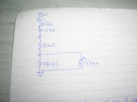
Build a representative test jig as per attached hand drawing. Place a voltmeter across the 470k resistor (sorry, it should be 420kOhm but i didn't have one available). This is the voltage that will be imposed on the g1 solely due to C36 leakage current.
I built it and checked by picking some unused axial polyester yellow 630V capacitors of various capacitances. Voltage across 470kOhms increases with PSU Vdc increasing and with capacitance increasing. But with healthy polyester capacitors this voltage will not be more that 1mVdc. (My bench PSU goes up to 60Vdc only)
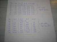
Then I checked with some paper coupling capacitors I had removed from a Hallicrafter S38 when I was renovating it. All were covered in wax and were in good physical condition. Now see on attached chart what it happens with voltage across 470kOhm (recorded voltage in mVdc).
In short, no need for precise measurements. The effect of a leaking capacitor on Vg1 will be obvious (and damaging)
George
If the transformer’s primary is open, there is no high voltage(232V) at the pentode’s plate of ECL82. This leaves the second grid (g2) which is sitting at 180V to play the positive terminal, pulling a lot of current. This current passes through R17 and R15 (check R17 for signs of overheat).
G2 current draw under normal operating condition as per schematic is roughly 1/3rd of cathode’s total current Ic.
Ic=Vc/R14=12.8V/375Ohm=34mA.Therefore Ig2 should be about 10mA under normal operating conditions .
Now if you want to measure Ig2 under this abnormal condition that your radio is at, just measure the dc voltage across R14 and divide by it’s resistance. (notice that specified Max continuous Ig2=20mA)
ECL82 pdf, ECL82 description, ECL82 datasheets, ECL82 view ::: ALLDATASHEET :::
Again, most probably the whole fuss must have started from a leaking C36 increasing the g1 potential.
You should check C36 for leakage current.
Build a representative test jig as per attached hand drawing. Place a voltmeter across the 470k resistor (sorry, it should be 420kOhm but i didn't have one available). This is the voltage that will be imposed on the g1 solely due to C36 leakage current.
I built it and checked by picking some unused axial polyester yellow 630V capacitors of various capacitances. Voltage across 470kOhms increases with PSU Vdc increasing and with capacitance increasing. But with healthy polyester capacitors this voltage will not be more that 1mVdc. (My bench PSU goes up to 60Vdc only)
Then I checked with some paper coupling capacitors I had removed from a Hallicrafter S38 when I was renovating it. All were covered in wax and were in good physical condition. Now see on attached chart what it happens with voltage across 470kOhm (recorded voltage in mVdc).
In short, no need for precise measurements. The effect of a leaking capacitor on Vg1 will be obvious (and damaging)
George
Attachments
gpapag, I have very basic knowledge. But this is good learning. I have removed all valves and speaker and cleaning the radio. Yesterday was searching internet on how to check capacitor leakage current ? And you posted very useful information. I thank very much.
An embarrassing moment for me. Yesterday I called radio repairing gentleman and asked if he had any spare output transformer, showed him model no., schematic and pictures on mobile. He said this Philips model had robust O/P transformer and chances of going open are less and asked me how did I checked. I said on MM 200 ohms setting. He said to check again with 2K MM setting. The impedance was 0.52K and 0.027K so he said transformer is OK. He offered to help if I take radio to him but he lives far away.
So I very much apologize if I have given wrong info about O/P transformer. Is transformer OK or open ?
thanks and 😱
Last edited:
- Home
- Source & Line
- Analogue Source
- Troubleshoot my Philips Valve Radio.