The center connection is aluminum. Difficult to solder it.
Voltage measurements as discussed. Black probe of Multimeter to chassis and red probe on each pin of ECC82
George
Voltage measurements as discussed. Black probe of Multimeter to chassis and red probe on each pin of ECC82
George
Yes gpgpag I shaved off little bit of aluminum with sharp blade to expose remaining part lead and soldered/glued. It measures around 36uf so OK i guess.
I have taken voltages at pins of ecl82. My multimeter is china made.
EZ80 and ECL82 attached. Speaker connected, Wire disconnected as shown in post #34. Bulb series tester. Bulb didn't lit. light glow on both valves. Here are voltages of valve ECL82 as seen from bottom and started from clockwise direction
(Pin1 = -0.08V) When multimeter probe touched to pin 1 hum sound on speaker. after some time This -0.08V became 0V. But hum remained.
(Pin2 = 16V DC)
(Pin3 = 0V DC)
(Pin4 = 0V DC)
(Pin5 = 0V DC)
(Pin6 = 214 DC)
(Pin7 = 199 DC)
(Pin8 = 0 DC)
(Pin9 = 77 DC)
Then I rememberd from schematic I saw Pin4-5 are heater and has separate direct supply from AC transformer so took AC measurements.
(Pin4 to Pin5 = 6.34V AC)
thanks and regards
You measured 199 V at ECL82's pin 7 and R15 still smokes? Was C34 connected while you measured?
Best regards!
Best regards!
No this was measured as instructed in post #34 wire disconnected. and in following posts it was mentioned after wire disconnected the R15 does not get hot. Yes C34 was connected.You measured 199 V at ECL82's pin 7 and R15 still smokes? Was C34 connected while you measured?
Best regards!
regards.
Last edited:
Very nice Hiten.
Anode voltages and pentode current are a bit high but it’s expected due to unloaded conditions (all other tubes are unplugged) and R15 is 1kOhm instead of 1.5kOhm.
Now, in this configuration, try to play some sound from the loudspeaker by connecting a signal source (signal generator, your mobile phone ect) at the PU input. Turn radio on, wait a few seconds, press the selector knob to PU and slowly turn radio’s volume up. I hope you will hear undistorted sound (you don’t need to make sound very loud). This is to confirm at this stage of troubleshooting before proceeding further , that the audio section of the radio is working.
Inform us of the outcome.
George
Agreed, your measurements sound reasonable.
As the frequency converter, IF and indicator tubes can't draw that much current to let R 15 smoke, I suspect that the one who had replaced that resistor not only chose the wrong value (which is critical for the hum compensation to work correct, btw), but also a too low wattage.
What's the voltage drop over the correct 1k5 R15 when all tubes are installed again?
Best regards!
Good News ! The Audio section is working.🙂
I connected CD player lineout with low volume setting of cd player + radio. Sound is coming out of speaker. As this is very old equipment I played for around 3/4 mins and put a small fan towards valves of the radio. then after about half an hour interval increased playing time. maximum I played around 5/6 mins. Sound quality is OK no distortion I noticed. When music is not playing there is hum if ear put close to speaker. But that may be due to shield wire I disconneceted from original wooden cabinet which had shield plates. I took video of it so you can check sound. Edited video to short duration of 15 sec. The speakers are turned over to limit the excursion. Ignore the crude wood box. It is not original it was build to protect delicate parts while turning over chassis while testing. Original cabinet had too small area to test.
Sound Check
Tell me what to do next please.
Kay I will do the test you mentioned.
thanks very much
Good. Next step.
Unplug the radio from mains.
Discharge C34, C35.
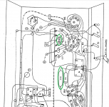
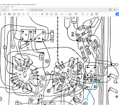
Discharge C20 C22 (see first attachment). Then measure them, not so much for exact capacitance but to confirm that they are not shorted . If they are shorted you have to replace them. If they are OK, then do the following:
Reconnect the wire that you had disconnected from the standoff of R16.
See 2nd attachment and disconnect the wire loop from the Q tab of the second IM freq transformer.
Install ECH81Next switch on radio.
Does R15 smoke?
George
Unplug the radio from mains.
Discharge C34, C35.
Discharge C20 C22 (see first attachment). Then measure them, not so much for exact capacitance but to confirm that they are not shorted . If they are shorted you have to replace them. If they are OK, then do the following:
Reconnect the wire that you had disconnected from the standoff of R16.
See 2nd attachment and disconnect the wire loop from the Q tab of the second IM freq transformer.
Install ECH81Next switch on radio.
Does R15 smoke?
George
Attachments
gpapag,
I disconnected one end of lead of capacitors C20 and C22. The C20 measures 92 nanofarads in my multimeter. Which translates to 92K pf. The schematics papers say 100K pf so i think this is ok.
But pardon my ignorance. The C22 reads 0.014 nanofarads which is 14 pf. The schmatics says 3E3 pf. Which I dont understand. What is E between 3s ? I also checked resistance for short. The C22 shows open even at 2000Meg on my multimeter. So I have stopped moving further. Kindly guide.
Hi Hiten
3E3 is 30nF. Measurement is way of. Chances are this capacitor is almost a short.
Remove it from circuit.
Check it for leakage. See schematic of post 18.
DC voltage value does not matter now, use what you have, even a 9V battery is OK.
Use only one resistor, any value you have above 10kOhm will do.
Measure DC voltage across the source and across resistor. Report values.
George
I think that neither C20 nor C22 can be the cause for a smoking R15. Look, they're both behind resistors of substantial values.
Of course they can be the reason for a non working frequency converter.
I've been thinking that one of the IF transformers might show a short to ground. But this can be excluded as the smoke reportedly stops when the RF tubes are out.
Best regards!
Of course they can be the reason for a non working frequency converter.
I've been thinking that one of the IF transformers might show a short to ground. But this can be excluded as the smoke reportedly stops when the RF tubes are out.
Best regards!
Some updates :
for capacitors that were hard to remove I used to desolder/disconnect one lead of capacitor and with little short wires (3 inches approx) used to test capacitance in MM. By this method this C22 capacitor used to show very negligible capacitance. Now I have removed it totally and measuring with 200nf and 20nf setting. It is showing no capacitance.
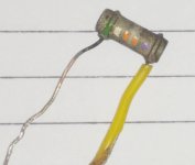
I have a DC adapter which shows 14v DC. A 14.7K measuring resistor is what I found to test. So C22 and 14.7k resistor in series other remaining capacitor lead to positive DC supply and remaing resistor lead to -ve supply I measured dc across the resistor it is showing 0 DC in All 20V, 2V, 200mV range. What does this mean ? I do have new 0.033uf non polar 250V capacitor with PPC code written on it. pl. find pic attached of old cap.
thanks for patiently helping me. Appreciate this very much.
Regards
for capacitors that were hard to remove I used to desolder/disconnect one lead of capacitor and with little short wires (3 inches approx) used to test capacitance in MM. By this method this C22 capacitor used to show very negligible capacitance. Now I have removed it totally and measuring with 200nf and 20nf setting. It is showing no capacitance.
I have a DC adapter which shows 14v DC. A 14.7K measuring resistor is what I found to test. So C22 and 14.7k resistor in series other remaining capacitor lead to positive DC supply and remaing resistor lead to -ve supply I measured dc across the resistor it is showing 0 DC in All 20V, 2V, 200mV range. What does this mean ? I do have new 0.033uf non polar 250V capacitor with PPC code written on it. pl. find pic attached of old cap.
thanks for patiently helping me. Appreciate this very much.
Regards
Attachments
Last edited:
OVdc reading means the capacitor is not leaking.
Nevertheless, since you have a new 33nF at hand put this new capacitor as C22 in the radio circuit. Reconnect C20 as well and continue as per post 48.
George
Nevertheless, since you have a new 33nF at hand put this new capacitor as C22 in the radio circuit. Reconnect C20 as well and continue as per post 48.
George
Hello gpapag, 🙂
Replaced old C22 with New cap. Reconnected wire R16 wire. Disconnected wire on 2nd IM transformer point Q. Installed valve ECH81. Tested with series bulb tester. speaker attached. volume low, Band selected SW1.
The bulb didn't lit. All three valves EZ80, ECL82 and ECH81 glow. Minor Hum when ear placed near speaker. There is no radio interferance sound like in shortwave radio. The R15 does not get hot even after more than one min. Probably kept on for one and half min. The R15 is cold or normal.
While taking valves which were kept aside the two valves (Dont know how I didn't noticed earlier) the remaining EBF89 has big dark silver band in mid region. Is it normal or is valve burnt ? The Magic Eye EM84 the top coating is clear. Probably gone ? kindly see pic. I do have extra EBF89. I guess we can carryon even without magic eye EM84. right ?
Attachments

The EBF89 doesn't look abnormal, just like a Philips made one. About the EM84 I'm not sure, but you'll see after you've put it back again.
Best regards!
Best regards!
All good up to now I would say.
Now unplug radio from mains. Discharge C34, C35 again.
Remove C24 and check for leakage as you did before. If it leaks, replace it. If it is OK, reinstall it. Then reconnect the HV wire loop at the 2nd IM transformer. Then plug in the EBF89. Now only the EM 84 is out of the circuit.
Switch radio on and check R15 for temperature.
Is it OK? If yes, push selector for MW or SW and slowly turn on volume. Do you hear hiss and static noise?, Try to tune to a station.
EM 84 I think has a cracked glass envelope. It seems milky (air inside), probably dead. It’s not important for the function of the radio. Do not plug it back in.
The hum you hear maybe from partially dried up C34, C35. You’d better replace those later on.
George
Attachments

Some faint hum, as he describes it, is rather normal for this kind of SE output stage.
Best regards!
Best regards!
Your C22 is ok with only a few picofarad capacitance. If I see it correctly in the schematic it sits at the anode of the triode in theECH81. If you change it to 30 nF, the oscilator triode in the ECH81 will not work anymore! This capacitor is a ceramic tube type and these have been very popular RF capacitors in tuners and IF stages. There have never been such capacitors of small size that had significantly more than a few nF, mostly < 1 nF.
Yes, Andreas thank you. You are most probably correct.
I looked at many schematics of radios with the ECH81.
Not many use a cap to ground there but the few that do, have this capacitor from 500pF to max 5nF.
So Hiten, as the original C22 was not leaking (*), please place it back in place.
(*) ceramic caps rarely leak. But when they fail, they fail dead short.
George
- Home
- Source & Line
- Analogue Source
- Troubleshoot my Philips Valve Radio.