Me too.gpapag, I have very basic knowledge.
But this is good learning.
Agreed. Thousands of people have start learning electronics while poking inside a table radio. Only one thing. Be careful with high voltages, especially main’s AC.
Take a half hour brake and watch this down to earth video. YouTube
Your radio doesn’t have live chassis. Still I strongly suggest get an isolation transformer and use it.
I'll be back soon
George
I watched the video. Good instructions on precautions. Cleaning of radio is done somewhat.
My friend has electronics shop. Though with lockdown sometimes for important things shops can be opened. Will see If I can get new capacitors and High wattage resistor soon.
Thanks Gentlemen.
addition : Also interested in measuring capacitor leakage. will see if I have proper caps resisistor and ps.
Last edited:
Hiten
Can you remove all the radio tubes and leave only EZ80 and ECL82 in place,turn the chassis so you have access to the bottom , locate all the pins of ECL82, turn equipment on, then carefully measure the voltage on all the pins of ECL82 with respect to ground?
Connect the black probe to the chassis, touch each pin of ECL82 with the red probe and record each measurement of the voltmeter. All pins Vdc except pin 5 (heater) which is Vac
George
Yes gpapag. Will do so very soon with all precautions. Will attach speaker, 2 valves mentioned etc. as was in first place.
Some newbie questions.
1) I presume selector knob position would not be important (Pickup, Medium Wave, Shortwave)? Volume knob at minimum ?
2) As mentioned in first post as I saw tiny spark in rectifier. Will it be any helpful if at first only rectifier valve is placed in and DC voltages of it measured ? Asking out of curiousity.
thanks
Hi Hiten
1) Right and yes.
2) I suggest no, because with a totally unloaded PSU, voltages will go up a lot and will overstress the old capacitors
Take care
PS. When I am testing aged equipment and I am at close distance to it, I wear protective glasses
George
1) Right and yes.
2) I suggest no, because with a totally unloaded PSU, voltages will go up a lot and will overstress the old capacitors
Take care
PS. When I am testing aged equipment and I am at close distance to it, I wear protective glasses
George
Yes I will be super extra careful. The video was very helpful. I do infact have protective eye glass wear.
thanks.
thanks.
taking little time. Please bear with me. I needed socket and switch for series bulb tester. and made little wooden protection cage for ferrite rod. as open chassis has one side heavy transformer and while tesing tips over.
few questions
1) the old original dual metal case caps C34 and C35 (32uf+32uf) had only one cap working and it measures 27uf. Long back someone put in new cap there and it is measuring 37uf. So now I have two old caps of 27uf+37uf, which might be leaking current.
I searched my parts and found new 82uf 400V cap. Should I replaces original 50yrs. old Philips (27uf) cap with this to be on safe side. ?
2) Tomorrow will be making all connections and power on with series bulb tester. I presume if bulb lights full bright I should immediately turn off. Correct ?
thanks for help
1) I wouldn't recommend that, at least not for the first capacitor. The EZ80 is rated for a maximum load capacitance of 50 uF, see http://www.r-type.org/pdfs/ez80-1.pdf , so when C35 > 50 uF you overload the rectifier valve.
Guys look at the schematic again. R15 gets hot, the problem is after R15 (+), not before. It supplies the rest of the radio after the audio output section. B1, B2, B4, C34 are suspect or one of the IF coils are shorted to ground. If B3 (screen grid short) is bad, R17 (3K3) would get hot and more than likely take out the screen grid. The power supply uses a winding in the OPT (S18) as a filter choke.
Edit: It might be a good idea to replace the EZ80 rectifier, since it sparked...
Edit: It might be a good idea to replace the EZ80 rectifier, since it sparked...
Last edited:
If the bulb glows bright it is indicating there is a short in the radio. However be reassured that it is also protecting the radio from further damage. You should quickly turn off the supply if this happens and search for the cause of the short.I presume if bulb lights full bright I should immediately turn off. Correct ?
Just in case you are unaware, you should use an old-style filament bulb with a wattage of the same order as the mains power consumption, in watts, of the radio itself.
Wayne, all these are correct.Guys look at the schematic again
...
Now Hiten faces difficulty to purchase any component replacement. That’s why I made the suggestion of removing all the other valves as a first step (successive elimination).
Voltage measurement at ECL82 pins will show if the PSU section is OK and if the output section is statically in order.
If this is so, next step will be to feed a test signal from the phono input to check for dynamic condition of the output stage.
After that, B2, then B1 and last the magic eye should be inserted one at a time and condition of DC voltages retested.
George
Galu,
Thanks. I have used 100watts filament bulb. Radio Service manual says it consumes 45 watts. so I guess this is OK
gpapag,
I did the series test. When a person like me who has little knowledge I took extra precautions. I used safety glass eyewear. Wore rubber slippers on feet. sat on wooden chair. Put on EZ80 and ECL82 tubes. Volume minimum. speaker attached.
powered on; 100watts bulb didn't lit at all (Radio consumes 45 watts as per manual). The ez80 and ecl82 small glow was present. within 5/6 seconds again light plume of smoke from resistor R15 Area. R15 gets very very hot within 5/6 seconds. I immediately shut it off. EZ80 also gets very hot within this small time.
offtopic question for learning purpose : As MarcelvdG has said this rectifier tube takes maximum 50uf. Now suppose my old capacitors are leaking currents. How about one I have new (82uf /400V) put in series. This will reduce capacitance but will it block leakages ?
Thanks all for your help you good people.
Last edited:
Hiten,
I'd desolder the positive terminal of C34 and leave the rest connected. If the magic smoke doesn't appear again when powering on, C34 is the culprit - and most probably it is indeed.
Is there really no chance to get a 32+32 µF/350 V or 50+50 µF/350 V can capacitor in India?
Best regards!
I'd desolder the positive terminal of C34 and leave the rest connected. If the magic smoke doesn't appear again when powering on, C34 is the culprit - and most probably it is indeed.
Is there really no chance to get a 32+32 µF/350 V or 50+50 µF/350 V can capacitor in India?
Best regards!
Thanks Hiten.
I would like to ask you to do one more action.
With the radio unplugged from the main’s and after discharging the electrolytic capacitors C34, C35.
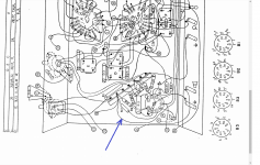
Please desolder the wire I point to at the attachment and remove it from the standoff where it connects with R16, R17. This way you stop the flow of High Voltage to the rest of the circuit. Cover it’s end with an isolation tape.
With only ECL82 and EZ80 installed, switch on the radio.
Does R15 get very hot again?
Does R17 get hot?
George
I would like to ask you to do one more action.
With the radio unplugged from the main’s and after discharging the electrolytic capacitors C34, C35.
Please desolder the wire I point to at the attachment and remove it from the standoff where it connects with R16, R17. This way you stop the flow of High Voltage to the rest of the circuit. Cover it’s end with an isolation tape.
With only ECL82 and EZ80 installed, switch on the radio.
Does R15 get very hot again?
Does R17 get hot?
George
Attachments
kay,
we are under lockdown. Electronics shop is just 5 mins. away but closed. Will do what you suggest.
gpapag,
will do so soon and update.
we are under lockdown. Electronics shop is just 5 mins. away but closed. Will do what you suggest.
gpapag,
will do so soon and update.
gpapag,
disconnected the wire you mentioned. Turned on the radio with series bulb tester. Tester Bulb does not lit up. Light glow in both EZ80 and ECL82 tube. Kept it on for around 30 seconds. R15 and R17 does Not get hot.
disconnected the wire you mentioned. Turned on the radio with series bulb tester. Tester Bulb does not lit up. Light glow in both EZ80 and ECL82 tube. Kept it on for around 30 seconds. R15 and R17 does Not get hot.
OK. will do so. Common of Multimeter to chassis and voltage on each pin of ECC82. correct ?Very good.
Now in that configuration, measure voltages at all pins of ECL82
George
kay
removed +ve of C34. R15 gets hot.
------
Will rearrange things as gpapag said and measure voltages at ecl82 pins.
removed +ve of C34. R15 gets hot.
------
Will rearrange things as gpapag said and measure voltages at ecl82 pins.
oops. a little mishap. Broke the lead of C34 from joint. Will see if it can be soldered back. Will update soon. Extremely sorry.
edit :
OK. Have joined the lead. But solder joint is just 0.5mm. Measured it and it is working. But very delicate joint. will see if I can glue it. pl. give time.
thanks and regards.
edit :
OK. Have joined the lead. But solder joint is just 0.5mm. Measured it and it is working. But very delicate joint. will see if I can glue it. pl. give time.
thanks and regards.
Attachments

Last edited:
- Home
- Source & Line
- Analogue Source
- Troubleshoot my Philips Valve Radio.