Thanks Kay, aboos & gpapag.
At 2nF setting in my cheap multimeter it is not showing any capacitance for C22. But I would replace new one with old one. Schematic Manual says C22 value as 3E3. Could it be they changed the value ? Looks like original and looks matches with other capacitors. What should be the value by looking at schematic and ignoring the service manual figure ? just curious.
I am running out of solder wire which already was not enough quantity. 😱
Probably govt. here will lift lockdown for shops in few days. I think I can manage meanwhile.
Best regards.
Looking at the circuit, I expect they mean 3.3 pF by 3E3. Like aboos wrote, it can't be in the nanofarad range as that would essentially AC short the oscillator tank. On the photo, you see that the three inner dots are orange orange white, which stands for 3.3 pF. I'm not sure whether the outer dots mean 5 % tolerance N750 or 500 V working voltage N750 or something else. C22 is part of a tuned circuit, so don't replace it if you don't really have to.
thanks marcelvdG.
I have put back original C22. C24 also tested by taking it out. It measures 6pf. (Original value 10pf). Leakage also checked there is 0vDC at 200mA and 2mA. C24 also put back in again.
I put back all valves. turned on radio within 5 seconds the R15 gets hot. As in previous test if kept on for more perioed from the area thin smoke comes. so i didn't kept it for long but it did get very hot even after 5 seconds. Antenna wire attached. No radio like static noise in any band.
I replaced EBF89. Getting same results.
I replaced ECH81. getting same results.
I put back original valves. And I connected CD player again with pickup input. The music does play.
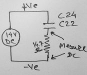
tested DC leakage of C22, C24 as pic attached
I have put back original C22. C24 also tested by taking it out. It measures 6pf. (Original value 10pf). Leakage also checked there is 0vDC at 200mA and 2mA. C24 also put back in again.
I put back all valves. turned on radio within 5 seconds the R15 gets hot. As in previous test if kept on for more perioed from the area thin smoke comes. so i didn't kept it for long but it did get very hot even after 5 seconds. Antenna wire attached. No radio like static noise in any band.
I replaced EBF89. Getting same results.
I replaced ECH81. getting same results.
I put back original valves. And I connected CD player again with pickup input. The music does play.
tested DC leakage of C22, C24 as pic attached
Attachments
To summarize your findings:
1. If magic eye, EBF89 and ECH81 are not plugged in - no hot resistor and you can play the NF part (ECL) and you get undistorted sound
2. You replaced both ECH81 and EBF89 and you get hot resistor (magic eye unplugged?)
As a next step, only install EBF89 (magic eye end ECH81 unplugged)
Then unplug EBF89 and install ECH81. Check resistor again.
Let us know the results of these two steps
yes aboos,
here are the steps history
1) EZ80, ECL82 attached. R15 resistor does not get hot. CD Player output to pickup input plays fine.
2) EZ80, ECL82 kept attached ECH81 added. R15 didn't got hot.
3) EZ80, ECL82, ECH81 kept attached ebf89 added. R15 gets hot.
4) replaced ECH81 (had Spare one) -> R15 gets Hot
5) replaced EBF89 (had Spare one) -> R15 gets Hot
6) Both original ECH81 and EBF89 put in.
7) How ever while all valves are put in. and cd player attached to pickup input. (Kept small fan on valve and R15 resistor)... played music... Music seems little less in volume...say about 10 to 20 percent. compared to only EZ80 and ECL82 attached.
Regards
addition : Also please note. I dont understand electronics but I guess gpapag has tested each section by removing supply to that part of circuit. So please take this in to account when following above history.
regards
regards
Now Hiten, after all wiring is resoldered to it’s original configuration, do these steps and answer briefly (with a yes or no) on each one.
1. Only EZ 80 and ECL82 installed. Does R15 smoke?
2. (EZ80, ECL82 installed) add ECH81 only. Does R15 smoke?
3. (EZ80, ECL82 installed) add EBF89 only. Does R15 smoke?
George
1. Only EZ 80 and ECL82 installed. Does R15 smoke?
2. (EZ80, ECL82 installed) add ECH81 only. Does R15 smoke?
3. (EZ80, ECL82 installed) add EBF89 only. Does R15 smoke?
George
So it seems that as soon as you plug in the EBF89 (either the old or the new one), the EBF draws too much current (resistor gets hot and volume of NF part goes down).
As next step, please check value of resistor R4. This resistor supplies the screen grid and if this resistor has a too low value, anode and screen grid current will go up significantly. You can easily measure the value in circuit (power off of course!!!)
As next step, please check value of resistor R4. This resistor supplies the screen grid and if this resistor has a too low value, anode and screen grid current will go up significantly. You can easily measure the value in circuit (power off of course!!!)
1. Only EZ 80 and ECL82 installed. Does R15 smoke? - Yes
2. (EZ80, ECL82 installed) add ECH81 only. Does R15 smoke? - Yes
3. (EZ80, ECL82 installed) add EBF89 only. Does R15 smoke? - Yes
Thanks
2. (EZ80, ECL82 installed) add ECH81 only. Does R15 smoke? - Yes
3. (EZ80, ECL82 installed) add EBF89 only. Does R15 smoke? - Yes
Thanks
1. Only EZ 80 and ECL82 installed. Does R15 smoke? - Yes
Thanks. Last troubleshooting steps I can think of.
Unplug radio from main’s.
Discharge C34 C35.
Leave only EZ80 and ECL82 installed.
Unsolder and disconnect from the circuit one end of capacitors C20, C22, C23, C24, C25, C26.
Switch on radio.
Does R15 smoke? If yes , then I can only think it is the second IM transformer that has it’s primary section shorted internally to chassis. You have to remove it and dismantle it.
If R15 doesn’t smoke: Unplug radio from main’s, discharge C34 C35.
Reconnect C20. Switch on radio. Does R15 smoke? If yes, replace C20 and reconnect it’s lose end.
If R15 does not smoke : Unplug radio from main’s, discharge C34 C35.
Reconnect C22. Switch on radio. Does R15 smoke? If yes, replace C22 and reconnect it’s lose end.
If R15 does not smoke : Unplug radio from main’s, discharge C34 C35.
Reconnect C23. Switch on radio. Does R15 smoke? If yes, replace C23 and reconnect it’s lose end.
If R15 does not smoke : Unplug radio from main’s, discharge C34 C35.
Reconnect C24. Switch on radio. Does R15 smoke? If yes, replace C24 and reconnect it’s lose end.
If R15 does not smoke : Unplug radio from main’s, discharge C34 C35.
Reconnect C25. Switch on radio. Does R15 smoke? If yes, replace C25 and reconnect it’s lose end.
If R15 does not smoke : Unplug radio from main’s, discharge C34 C35.
Reconnect C26. Switch on radio. Does R15 smoke? If yes, replace C26 and reconnect it’s lose end.
After all this, logic says that switching radio on R15 will not smoke.
Then switch off radio and install EBF89. Switch radio on. Does R15 smoke? If yes, Switch off and check If soldering tags 1, 6, 8 at the base of the tube touches a ground wire.
If R15 does not smoke switch off radio and install ECH81. Switch radio on. Does R15 smoke? If yes, Switch off and check If soldering tags 1, 6, 7 at the base of the tube touches a ground wire. Or it is the second IM transformer having it’s secondary section shorted internally to chassis. You have to remove it and dismantle it.
I can not think of anything else
George
George I cant thank you enough for your help.Leave only EZ80 and ECL82 installed.
Unsolder and disconnect from the circuit one end of capacitors C20, C22, C23, C24, C25, C26.
Switch on radio.
Does R15 smoke? If yes , then I can only think it is the second IM transformer that has it’s primary section shorted internally to chassis. You have to remove it and dismantle it.
I placed EZ80 and ECL82 only. Disconnected one end of C20, C22, C23, C24, C25, C26. The resistors R15 gets hot within 5 seconds. So didn't go further.
Which one is Second IM transformer ? Is it S 15/S 16 shown in the schematic ?
Regards
Which one is Second IM transformer ? Is it S 15/S 16 shown in the schematic ?
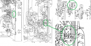
That's correct Hiten. See attachment .
The ends of the two internal coils are coming out at the bottom side at the following terminals:
Primary coil: P and Q
Secondary coil: L and T
Now, unplug radio from mains.
Discharge C34 and C35.
Unnsolder and lift wire loop from terminal Q.
Use the ohm meter. Black probe to the chassis, red probe to each of P, Q, L, T terminals.
Does it read a short to the chassis on any of these terminals?
George
Attachments
Hi,
I disconnected wireloop to Q terminal. Checked Chassis to the terminal P,Q,L and T. It does not show short. It Shows Open in 200 ohms range.
I checked resistance of primary coil P-Q it shows approx. 11.2 ohms but Secondary coil L-T shows open. (Both on 200ohms Multimeter range)
regards
I disconnected wireloop to Q terminal. Checked Chassis to the terminal P,Q,L and T. It does not show short. It Shows Open in 200 ohms range.
I checked resistance of primary coil P-Q it shows approx. 11.2 ohms but Secondary coil L-T shows open. (Both on 200ohms Multimeter range)
regards
.... pl. wait. .....
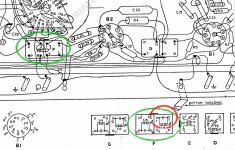
I looked at wiring diagram in the manual. See attched pic. The transformer is shown in green circle on left. At bottom the same transformer 'F' is showing where coils are.
The bottom (green circle) transformer inards shows coils as P-Q and 1-T. So I measured 1-T it shows around 7/8 ohms.
I looked at wiring diagram in the manual. See attched pic. The transformer is shown in green circle on left. At bottom the same transformer 'F' is showing where coils are.
The bottom (green circle) transformer inards shows coils as P-Q and 1-T. So I measured 1-T it shows around 7/8 ohms.
Attachments
Good News !!!
The radio is working. I decided to check voltages on each valves according to schematic So wanted R15 resistor badly so that while it gets hot slowly I can measure. Somehow I got brand two new 33uf Caps (C34+C35) and 470 ohms 10 watt resistor which I put in series with 1K Resistor. Here is the sequence.
I replaced R15 and C34 + C35. No Sound, Disapointed I changed each valve with another one to test. No result. Put back original valves. Decided to check Rectifier valve voltages. Rectifier Pin 3 had around 100V so Checked Transformer Secondary. It showed varying voltages. around 260V/280V. (My multimeter is cheap chinese one) So I turned off everything. Checked new parts connections etc. and started again. The radio started working. The R15 Resistor is not getting that hot (1K + 470 ohms in series) Played for 3/4 mins. with gap of around 15 mins. Once there were very low level feeble fire cracker type sounds but radio kept working. So turned it off. Played in again after 3/4 hours. Now it is working. Now time to clean it do the tid bits and knickknacks and reassemble it. Had also posted this problem in another forum.
I thank everyone. Specially George for his time and effort. I understand doing online troubleshooting that to without the device in front of him and person like me who has half knowledge is very difficult. So I thank you george once again for your patience and guidance. 🙂
Thanks to Philips Who made products which lasts 50 years. Will post picture after assembling the radio.
Now Question is since I only replaced R15 and C34,C35 capacitors.
Why did the resistor R15 got hot ?
Is it due to combined problmes like leaking capacitors and low value resistor ?
There is thermal fuse between windings of power transformer. Could it be intermitent ?
Thanks and Best regards
Last edited:
That's exactly what I suspected yet in #33 as the most obvious, most common cause. But alas he didn't listen...🙄
Best regards!
Best regards!
Kay
I did carried out your suggestion and posted results in post #39. That resistor still got hot. And as for the new C34+C35 as I said all shops were closed. I sincerely thank everyone who helped.
Regards.
addition :
Everyone,
I have kept original capacitors as it is. Do tell if any test on them can reveal the fault. Also remember I did changed R15. by connecting 1K to 470ohms in series both 10 watts.
Last edited:
Ok, 10+ watts as R15 is brute force. Especially if they're these square cement bunkers they never will let that magic smoke out.
Usually the wattage of a resistor in this role is 2 watts, carbon film, and it won't smoke if there's no fault within the circuitry it is feeding.
Best regards!
Usually the wattage of a resistor in this role is 2 watts, carbon film, and it won't smoke if there's no fault within the circuitry it is feeding.
Best regards!
- Home
- Source & Line
- Analogue Source
- Troubleshoot my Philips Valve Radio.