Don't forget that a fullrange can usually make a rather good mid. Without knowing what you have, I can't make a more detailed suggestion. But the Duelund theory is right.Perfect, I have been craving base (my Full Range is wonderful but lacks bass) and good mids are always a must.
I actually may build this one.
An externally hosted image should be here but it was not working when we last tested it.
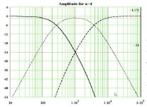
That's one of the slopes you can do, if you do this 4th order and time aligned to whatever degree is practical. I like that one. 🙂
Ok, can you make it easy for a newbie to XO's to understand the above figure?
Practically speaking, if I set my center freq at say 1500Hz, then:
Bass driver needs to be LR2 at 750Hz
tweeter needs to be LR2 at 3kHz
mid needs to have BW1 HPF at 750Hz & BW1 LPF at 1.5kHz?
An externally hosted image should be here but it was not working when we last tested it.
Practically speaking, if I set my center freq at say 1500Hz, then:
Bass driver needs to be LR2 at 750Hz
tweeter needs to be LR2 at 3kHz
mid needs to have BW1 HPF at 750Hz & BW1 LPF at 1.5kHz?
We are all newbies to audio really. 🙂
Thing is, all designs are a compromise IMO. Certain laws of physics say say you can't do an even order filter (LR2 and LR4) two way without a power suckout at crossover. Above and below axis. Or you do BW3 and accept that it lobes above or below axis.
Steen Duelund was a bit of a genius in realising that a three way has to hang together with all three drivers and depends on time alignment. If you do it right, you might go 8", 4" and 1" and get everything nicely aligned. And in a way, there is only ONE crossover frequency. Usually around 1.5kHz.
There are various solutions in 4th order Duelund theory. A wide midrange, or one that just fills a bit of a gap between woofer and tweeter. The wide midrange is mostly 12dB/octave second order. Simply speaking, some of the crossover components become redundant.
Troels Gravesen designed the hugely popular SEAS 3 Way Classic.
It leads to a third order tweeter to align phase.
His wheeze was to then time align the tweeter into the Scanspeak 3W Discovery and use LR2.
When you build a 3 way, you can almost predict the success of the sound from how closely the curves approximate Duelund theory. I think the 3W discovery inevitably looks better than the SEAS 3 way classic. But both good. And both do a great job of aligning phase on ALL THREE drivers.
Without overcomplicating things, there are some other shallower and steeper optimised solutions too. But this works.
Attachments
Last edited:
When you build a 3 way, you can almost predict the success of the sound from how closely the curves approximate Duelund theory.
Somebody had mentioned before, not all designs follow Duelund.
Duelund requires perfect midrange which is rare and expensive, so it is easy to understand that most designs are not Duelund. Even in high-end where midrange is capable, I think Duelund is not popular (Can you explain why?).
Alex, I looked into the theory of the B&O filler driver, and it's not what Steen Duelund worked toward. The filler driver was an attempt to get linear phase (or good impulse response) by wiring the LR2 bass and tweeter out of phase and filling the null with the shallow mid filter which was actually 90 degrees out of phase, or "in quadrature" as Lynn Olson remarked. It was a second order all pass overall.
I always thought the tweeter and woofer were in-phase? That's how you get the null?
And filling it with a BW1 for the midrange?
Anyways, great discussion. 🙂
Can someone show the step response of TG 3WClassic?
I understand the difficulty of 3-way pasive systems yes. But modern dsp gives more freedom for eg. driver choices because it is so easy to shape responses and delays.
BTW Audax HM100Z0 is a fine 4" mid!
I understand the difficulty of 3-way pasive systems yes. But modern dsp gives more freedom for eg. driver choices because it is so easy to shape responses and delays.
BTW Audax HM100Z0 is a fine 4" mid!
I don't want to derail the discussion here, but this is a very contestable claim. As I understand these notions, there is a major difference between a mathematical equation or system being 'true' vs. a scientific theory being 'true.' Put crudely, mathematical 'truths' only need to be consistent and coherent (following an a priori logic of deductive entailment from a set of given or 'hypothesized' conditions), and don't depend on empirical evidence, while the scientific 'truths' must be supported (or supportable) by empirical evidence (following the a posteriori logic of abduction and induction, as well as the a priori logic of deductive entailment). Thus, just because something is 'true' mathematically (or logically), it doesn't follow that it will also be 'true' empirically.What is impressive about the maths of it, is that this theory will still be true in a thousand years time! 😎
Thankyou for your interest, ranhaber.
On most accounts of the empirical world it is always possible to come across new information that will cast doubt upon prevailing scientific theories, and while it may be okay to claim that a mathematical conclusion will be true in a thousand years time, it may be somewhat more presumptuous to say that of a scientific conclusion.
I always thought the tweeter and woofer were in-phase? That's how you get the null?
And filling it with a BW1 for the midrange?
I believe this is true.
Can someone show the step response of TG 3WClassic?
I think it will be a peak followed by a dip and a rise - not a perfect right triangle, which I think can only be achieved by a 3-way with LR2/BW1/LR2 hole-filler XO.
I am getting ready to set up a (budget) test bed for playing with cool time-aligned 3-way XO's. I have a 12in woofer (Beta 12cx or dual TB W5-876SE's), an assortment of great wide bandwidth full range drivers for the mid (Vifa TG9FD, TC9FD, SS 10F/8424, etc., and if needed I even have a Heil AMT for the tweeter), and a Dayton DC28F-8 silk dome tweeter. I will be using a miniDSP in 1x4 mode and tri-amping, so I will have any XO at my disposal. Plan to put the woofer and mid in simple open baffle, or maybe sealed for the woofer. Based on the drivers I have, I am guessing that the singular XO freq will be 1500Hz. If anyone has pointers or advice, please let me know.
I really want to learn how to play with these Duelund XO's or the B&O hole-filler XO.
The DISCOVERY 3-way seems to be a good place to start and it looks like a solid 1500Hz XO point:
Last edited:
XRK 971,
What I am really interested in is the off axis behaviour from 0-90degrees in 5 degree increment, both horizontally and vertically, inyour experimental MiniDSP' 3 way setup
Looking forward to the further findings of your experiments. The Discovery seems to have a somewhat prominent woofer output from 65 Hz to 900 Hz in comparison with mid and tweet. Curious to learn how that compares with totally flat.
Good Luck,
Eelco
I believe this is true.
I think it will be a peak followed by a dip and a rise - not a perfect right triangle, which I think can only be achieved by a 3-way with LR2/BW1/LR2 hole-filler XO.
I am getting ready to set up a (budget) test bed for playing with cool time-aligned 3-way XO's. I have a 12in woofer (Beta 12cx or dual TB W5-876SE's), an assortment of great wide bandwidth full range drivers for the mid (Vifa TG9FD, TC9FD, SS 10F/8424, etc., and if needed I even have a Heil AMT for the tweeter), and a Dayton DC28F-8 silk dome tweeter. I will be using a miniDSP in 1x4 mode and tri-amping, so I will have any XO at my disposal. Plan to put the woofer and mid in simple open baffle, or maybe sealed for the woofer. Based on the drivers I have, I am guessing that the singular XO freq will be 1500Hz. If anyone has pointers or advice, please let me know.
I really want to learn how to play with these Duelund XO's or the B&O hole-filler XO.
The DISCOVERY 3-way seems to be a good place to start and it looks like a solid 1500Hz XO point:
Did you read the original Steen Duelund paper?
http://www.diy-audio.narod.ru/litr/duelund-filter.pdf
Steen Duelund in his paper said:I have used this filter once, in a huge construction with the most fantastic result. And it
will by used again.
I wasn’t happy then, with the use of so many components, even if they were the best of
my knowledge at that time. There has to be 6 of the kind on each unit, besides those
used to correct the unit’s impedance and peaks. It was really overwhelming.
Normally one would say, “forget it”, but here we come to the next point of the neverending
story - the components.
If we can develop these with a minimum of errors, or with defects, that at least serves
the perception of sound, we are on the right track. For details on that matter you must
look under “Components”.
So even Mr. Duelund figured there were a lot of components needed 😀.
But the lesson from this would be it isn't as easy as just choosing the right slopes in MiniDSP. It's the actual acoustic response that counts as it does with all crossovers. But this one will be harder to get right than that first order slope.
Here's another interesting view on things: Duelund and Beyond
If you look at that text you'll notice this still hasn't got the Step response indicating linear behavior. There's a phase rotation at the crossover frequency.
But no ringing and smooth phase response which was the main point if I interpret the Duelund paper right.
Thanks for the links Wesayso. Especially this one: Duelund and Beyond
I will have to get Mathcad fired up and delve into the complex filter theory again and see if I can generate and play with some of this.
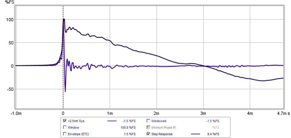
I do realize that it is the overall response that counts. However, my one brief encounter with a simple passive BW1 xo using a coil and cap with padding resistors, despite the overall acoustic response being closer to 2nd order overall after enclosure and electrical are added - still resulted in a decent step response.
http://www.diyaudio.com/forums/full-range/273524-10f-8424-rs225-8-fast-ref-monitor-44.html#post4345937
Test cabinet (ignore SS 10F mounted on main baffle) with external BW1 passive XO:
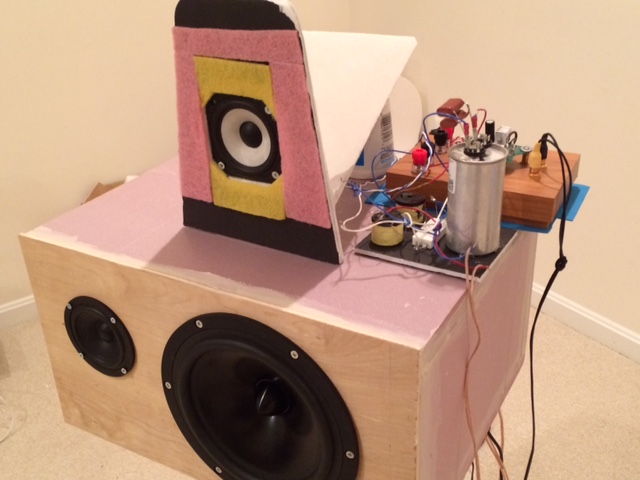
Acoustic response:

Step response:
I will have to get Mathcad fired up and delve into the complex filter theory again and see if I can generate and play with some of this.
An externally hosted image should be here but it was not working when we last tested it.
I do realize that it is the overall response that counts. However, my one brief encounter with a simple passive BW1 xo using a coil and cap with padding resistors, despite the overall acoustic response being closer to 2nd order overall after enclosure and electrical are added - still resulted in a decent step response.
http://www.diyaudio.com/forums/full-range/273524-10f-8424-rs225-8-fast-ref-monitor-44.html#post4345937
Test cabinet (ignore SS 10F mounted on main baffle) with external BW1 passive XO:
Acoustic response:
Step response:
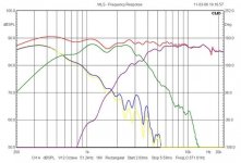
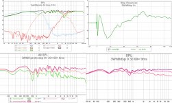
I had this proto some time ago. Double 8" SEAS, Audax 4" and Fountek ribbon. Minidsp and in this version LR4 filters. Bass response is sloping too fast but it comes from vertical directivity of the double system. Center xo close to 1500Hz. Notice the excellently smooth horizontal directivity! Sound was fine but I had just one speaker.
-
Oh, I tried also LR2 but it didn't sound so good. Perhaps it was just careless fine-tuning but I have had similar experience with other projects. Too much ovelapping will lead to more IMD, demand for perfect slopes is higher?
-
Oh, I tried also LR2 but it didn't sound so good. Perhaps it was just careless fine-tuning but I have had similar experience with other projects. Too much ovelapping will lead to more IMD, demand for perfect slopes is higher?
Attachments
Last edited:
Hi xrk971,
If you just want to experiment with these filter types to see what they do and what is achievable, you could simply connect 3x10K resistors to the outputs of your miniDSP and tie the 3 ends together to sum the three outputs. This should simulate the summing of 3 acoustic signals. With a little 101 trigonometry, you could adjust the output delay of the appropriate channels to simulate different acoustic path lengths for estimating the vertical polar response as well.
The output level from any one channel as seen at the junction of the 3 resistors will be reduced in magnitude to about 300mV relative to 0dBFS, but this level should still be adequate for your sound card.
Doing it like this will avoid many issues like BSC and baffle edge diffraction ripple etc.
Peter
Thanks for the tip to do a hard electrical sim in miniDSP. Interesting idea but ..,
I could simulate it in Mathcad or Akabak just as well as using resistors as a summing junction. Where is the fun in that though? In Akabak, I would be able to model the baffle step and diffraction of the edge, placement of drivers, and use real TS parameters. In fact I have done this already and it works quite well. A lot of fun. So I think I am ready to try with real drivers. The problems I see ahead for me are the fact that drivers are not smooth and flat. The have breakup peaks and they have dips. The enclosure also has its own fall off if you are not far away enough from xo point. So often I have to apply judicious EQ to get the driver response reasonably flat before trying to apply the textbook slopes.
I could simulate it in Mathcad or Akabak just as well as using resistors as a summing junction. Where is the fun in that though? In Akabak, I would be able to model the baffle step and diffraction of the edge, placement of drivers, and use real TS parameters. In fact I have done this already and it works quite well. A lot of fun. So I think I am ready to try with real drivers. The problems I see ahead for me are the fact that drivers are not smooth and flat. The have breakup peaks and they have dips. The enclosure also has its own fall off if you are not far away enough from xo point. So often I have to apply judicious EQ to get the driver response reasonably flat before trying to apply the textbook slopes.
Why Duelund Filter Is Not Popular
Duelund's Idea: Duelund wanted a multi-way speaker where drivers are ALL in phase at all frequency (as exactly represented by his Mathematical model).
Regarding the above transfer function, to be a Duelund's filter, the bass/tweeter slope must be approximately LR4 (or staggered LR2) and the midrange must be approximately LR2 bandpass. What we see in Troel Gravesen's is a full LR2.
I don't know the period Duelund developed his idea but I believe that back then, so little was known about speaker design and behavior (may be even before Thiel and Small?).
Knowing better about variables that will affect speaker performance, will put Duelund's theory into a test. Because Duelund only cared about flat frequency response and phase coherence at all frequency. Many other things are excluded may be because there was no information back then.
For example, Duelund's mathematical approach with limited variables, will require that the listening distance is also a constant. In other words, it is only true when you stick your ears at a certain location around the speakers. This is not preferable to many of us. Today, we (well, I do) care more about off-axis performance.
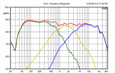
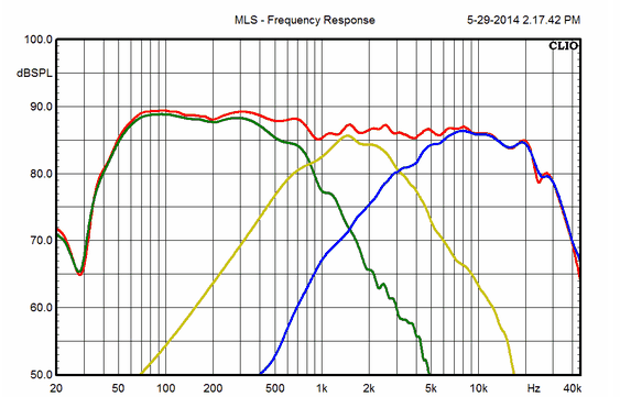
OK, last part of this look at the ScanSpeak-3W-Discovery.
Troels doesn't time align the bass and mid, because the error in wavelength is small. What he goes for is roughly this:
An externally hosted image should be here but it was not working when we last tested it.
Duelund's Idea: Duelund wanted a multi-way speaker where drivers are ALL in phase at all frequency (as exactly represented by his Mathematical model).
Regarding the above transfer function, to be a Duelund's filter, the bass/tweeter slope must be approximately LR4 (or staggered LR2) and the midrange must be approximately LR2 bandpass. What we see in Troel Gravesen's is a full LR2.
I don't know the period Duelund developed his idea but I believe that back then, so little was known about speaker design and behavior (may be even before Thiel and Small?).
Knowing better about variables that will affect speaker performance, will put Duelund's theory into a test. Because Duelund only cared about flat frequency response and phase coherence at all frequency. Many other things are excluded may be because there was no information back then.
For example, Duelund's mathematical approach with limited variables, will require that the listening distance is also a constant. In other words, it is only true when you stick your ears at a certain location around the speakers. This is not preferable to many of us. Today, we (well, I do) care more about off-axis performance.
The theory of acoustic centres is a bit peculiar in practise. A cone is not a point source for one thing, and as I hinted earlier, LR filters don't actually work very well on phase alignment in two ways. Surprisingly, Butterworth and Tchebycheff slopes are better.
Although I don't always agree with you S7, on this point I wholeheartedly agree ��
Although I don't always agree with you S7, on this point I wholeheartedly agree ��
Hi Mondogenerator, is that regarding LR2 only or also LR4?
LR2/LR4 seem to be used very often probably because of the flat sum behavior. But when I build a crossover, I'm not dictated by filter types, I'm free, because with a software, we don't need to solve mathematical formula.
Most often I came up with close to LR4 when steep crossover is needed (not really LR4 as I use notch filters to tailor the slope, or even make it "steeper" a-la LS3/5A. Conical or something i forget what people call it), or happen to be a BW when shallow slope is what I'm after. Never LR2.
Did you manage to optimize Troels 2way filter?
Are there any commercial duelund speakers on the market?
Are there any commercial duelund speakers on the market?
Simulations and minidsp output are just mathematical excersises! In real world th acoustic output is what matters. Drivers are not linear even on-axis etc.
There are many ways to skin a cat...
I have noticed that many well regarded high-end 3-way speakers are all-LR4 nowdays, like Magicos, Revels. Step response is zigzag but sound is pure silk!
There are many ways to skin a cat...
I have noticed that many well regarded high-end 3-way speakers are all-LR4 nowdays, like Magicos, Revels. Step response is zigzag but sound is pure silk!
- Status
- Not open for further replies.
- Home
- Loudspeakers
- Multi-Way
- Troels Gravesen Time Aligned 3 way published.