Troels design reminds me somewhat of the physically time aligned Mission 770 Freedom speakers. Albeit, the latter were 2-ways.
These?
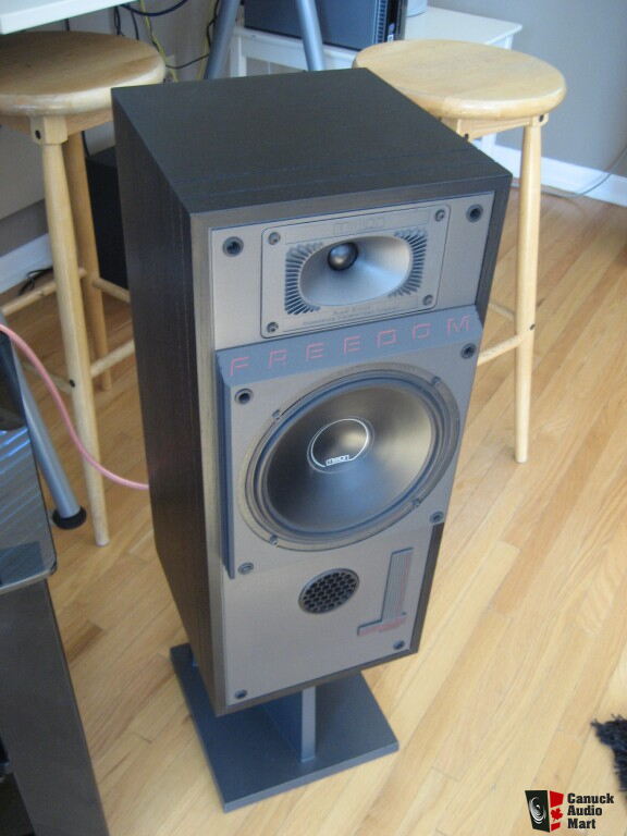
They are hideous… 😱
Alex
I appreciate what Alex was saying about the filler driver concept in two ways. It is neat mathematically, but near impossible in practise. Lynn Olson thought it was broken when I asked him about it.
As I said, i only got as far as the theory! I did a search for midrange drivers that might qualify, and came up with the grand total of zero.
On top of that, the eventual realisation of the impossibility of getting good enough (read "exact") phase matching even on axis, never mind off-axis, for linear phase crossovers was what put me off the whole crazy quest, and eventually landed me on three-way Linkwitz-Riley.
Alex
Joachim Gerhard (who I suppose qualifies as a DIY man here...😀) has a lovely sloped baffle in his SEAS based commercial Anima speaker. He said he used third order butterworth:
An externally hosted image should be here but it was not working when we last tested it.
I used a sloped baffle in my own three-ways to get time alignment between mid and treble, and my recent measurements seem to confirm that this worked quite well. The drawback in this case, though, was that the listening location is then very much below the tweeter axis, resulting in some quite serious HF loss above 5kHz.
Alex
These?
They are hideous… 😱
Alex
Not when covered with the proper grille.
............
Sophisticated loudspeaker design/simulation programs use actual measurements with distance data, and provide means to phase matching (LSPcad, SoundEasy) - if done well!
[/URL]
I presume Troels has all of those tools.
I used a sloped baffle in my own three-ways to get time alignment between mid and treble, and my recent measurements seem to confirm that this worked quite well. The drawback in this case, though, was that the listening location is then very much below the tweeter axis, resulting in some quite serious HF loss above 5kHz.
Alex
You are at the difficult end of the Duelund three way spectrum here Alex. Ideal slopes get nearer LR2 and the mid is struggling. Well, that's the theory. 😀
An externally hosted image should be here but it was not working when we last tested it.
I quote from Steen Duelund's paper below.
Attachments
Time aligned ! .. Mr Peabody: set the Wayback Machine to 1979!
Haven't seen 'this' theory for some time.
Clearly if one waits long enough that old frock in the closet may come back into fashion.
Still not sure re Mr Graveson's designs.
I meticulously built one of his crossover creations.. once.
It proved to be inferior sounding to the stock/oem crossover, in my drivers and my ears... at least.
Others also concurred, so not entirely my perceptions alone either.
Definitely took the fan out of fanboy for me.
Steve, I remember B&O speakers around 30 years ago touting a "filler" driver and time alignment. Crossover curves looked very much like what you show. They didn't sound bad, and we sold some.... The claim was that you could produce a decent looking square wave...
When measuring my 2 way active speakers the results is 0.14ms for the tweeter delay. Seems small but when switching it off the unity of the two drivers go away and you can hear the tweeter separately. Quiet cool you can hear that.
Last edited:
You are at the difficult end of the Duelund three way spectrum here Alex. Ideal slopes get nearer LR2 and the mid is struggling. Well, that's the theory. 😀
I quote from Steen Duelund's paper below.
Yes, but maybe I wan't clear in my post - in this case I use a proper three-way LR4 crossover. I don't think of the midrange as a filler driver, since the crossover points are three octaves apart.
Alex
So why don't you dispose them along an arch ??
😱
Because I hadn't appreciated the drop off off axis at the time, and I can't bring myself to build new boxes…
Alex
I think the whole issue of time alignment is made up by putting a cross over in a frequency range where it should not be !
The engineer created a 'problem' to be able to create a 'solution' 😛
"The phase coherence of harmonics in the vocal formant range, ~630Hz to 4000Hz"
http://www.diyaudio.com/forums/multi-way/223714-phase-coherence-harmonics-vocal-formant-range-630hz-4000hz.html
.
The engineer created a 'problem' to be able to create a 'solution' 😛
"The phase coherence of harmonics in the vocal formant range, ~630Hz to 4000Hz"
http://www.diyaudio.com/forums/multi-way/223714-phase-coherence-harmonics-vocal-formant-range-630hz-4000hz.html
.
Bare, why didn't you send a builders comments to Troels if you thought his filter was worse than your original? 😀
Alex, I looked into the theory of the B&O filler driver, and it's not what Steen Duelund worked toward. The filler driver was an attempt to get linear phase (or good impulse response) by wiring the LR2 bass and tweeter out of phase and filling the null with the shallow mid filter which was actually 90 degrees out of phase, or "in quadrature" as Lynn Olson remarked. It was a second order all pass overall.
Steen Duelund was trying to get all 3 drivers working with the same phase, so it all integrates nicely and has an allpass or flat frequency response. I've been struggling to understand his filters, but they are 4th order at heart. And he doesn't attempt to get linear phase, but rather phase alignment.
So firstly some theory:
I'll apply it in the next post, so bear with me again! 🙂
Alex, I looked into the theory of the B&O filler driver, and it's not what Steen Duelund worked toward. The filler driver was an attempt to get linear phase (or good impulse response) by wiring the LR2 bass and tweeter out of phase and filling the null with the shallow mid filter which was actually 90 degrees out of phase, or "in quadrature" as Lynn Olson remarked. It was a second order all pass overall.
Steen Duelund was trying to get all 3 drivers working with the same phase, so it all integrates nicely and has an allpass or flat frequency response. I've been struggling to understand his filters, but they are 4th order at heart. And he doesn't attempt to get linear phase, but rather phase alignment.
So firstly some theory:
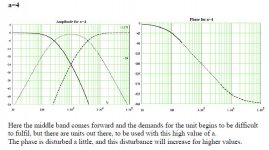
(Steve remarks: Reference the relative size of drive units in a LR2 filter. Interesting, eh?)
This version is, as said earlier, perfect. It can be difficult for the unit used, to fulfil the
demands, if the difference in size between the units used is too big. A 6-inch bass/mid
with 1-inch treble is commonly used, but in my view the difference in size must be
decreased.
(Steve remarks: Now talking about his 4th order bass and treble with a midrange with gentler 2nd order slopes for which I show the formula below as an image, because the formatting of formulae is difficult.)
Advantages.
1. Its summarised amplitude response is always exactly 1.
2. The units are in phase with one another at all frequencies if (a) is bigger than or equal to the Square root of 2.
3. The step response is for (a) bigger than 2 without ringing.
4. Its turn of phase can be chosen as a point to start.
5. Its amplitude slope is rounded - slowly reaching its highest slope. The higher (a) value the slower rounding.
6. The units have great overlap (correctional network is unavoidable).
7. When playing it is impossible subjectively to identify the single units as separate sources of sound.
8. It can be realised in full and doesn’t demand more of the units than it should be possible for them to deliver - dependant of the (a) value.
Disadvantages.
1. The displacement to one another is critical as they work in phase. They must fit within 1 mm from listening position. You are therefore forced to house the units in three separate cabinets, so you can optimise the distance to your listening position. In my views it really is an advantage. It is for you to judge. How you find these positions is described under – “How to build to the limit”.
Again all you need is the curvature of the amplitude response for the three units.
But here we have a problem, I’m not to choose - you are. Therefore you must calculate yourself, if you want to see the possibilities.
In general it can be said, that the bass and treble roll off are 24 dB per octave asymptotically ruled by it Q, and likewise the middle but with 12 dB per octave.
The factor (a) decides it all.
The bandpass part -(a2-2)s2 has to be negative, so (a) has to be greater than or equal to the square root of two.
I'll apply it in the next post, so bear with me again! 🙂
Attachments

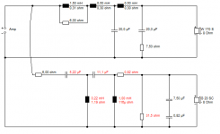
It's better to walk before you run, so what I did here is try to design a Steen Duelund two way. 6" paper bass plus 1" soft dome tweeter. It looks like this with 4th order slopes:
And we're time aligning it with a 3cm. recess on the tweeter:
Now Steen always said you need to correct impedance, so I've done this with correct Zobels. I've also tried to take bafflestep out of the equation with a 6 ohm resistance approach, if you follow.
I pretty much let the Boxsim optimiser take it from there, and what it came up with was interesting. It was fourth order on bass and tweeter and it liked the Zobels. And it didn't like notches at all with time alignment! 😎
So we seem to have a new design to try. It looks very good to me on phase, albeit the bright midrange frequency response needs work, but we can refine that later.
An externally hosted image should be here but it was not working when we last tested it.
And we're time aligning it with a 3cm. recess on the tweeter:
An externally hosted image should be here but it was not working when we last tested it.
Now Steen always said you need to correct impedance, so I've done this with correct Zobels. I've also tried to take bafflestep out of the equation with a 6 ohm resistance approach, if you follow.
I pretty much let the Boxsim optimiser take it from there, and what it came up with was interesting. It was fourth order on bass and tweeter and it liked the Zobels. And it didn't like notches at all with time alignment! 😎
So we seem to have a new design to try. It looks very good to me on phase, albeit the bright midrange frequency response needs work, but we can refine that later.
Attachments
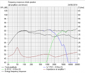
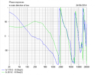
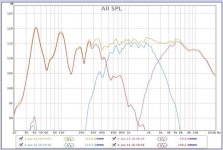
I've tidied up the design a bit here. I couldn't help noticing that the second section of the 3cm. time aligned tweeter filter wasn't doing much. 🙂
Here's the drive units:
W 170 S - 8 Ohm
G 20 SC - 8 Ohm
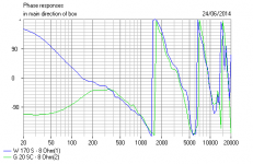
The 4th order electrical filter is very nice indeed for the bass. But clearly the Fs 1.9kHz tweeter has some natural rolloff which we can exploit for a simpler filter. It still looks good on phase and approximates the LR4 curve that is our guide here:
Steen does say he doesn't like 6" plus 1" tweeter. And the Fs resonance is higher than we would like ideally for low distortion. So I'm thinking that this 29mm SEAS jobbie would be closer to his ideas here:
H1318-06 29TFF/W
Being flatter lower, it gives a better overlap that would probably need a 4th order electrical filter and be nearer some sort of Duelund "perfect phase alignment at all frequencies".
An externally hosted image should be here but it was not working when we last tested it.
Here's the drive units:
W 170 S - 8 Ohm
G 20 SC - 8 Ohm
The 4th order electrical filter is very nice indeed for the bass. But clearly the Fs 1.9kHz tweeter has some natural rolloff which we can exploit for a simpler filter. It still looks good on phase and approximates the LR4 curve that is our guide here:
An externally hosted image should be here but it was not working when we last tested it.
Steen does say he doesn't like 6" plus 1" tweeter. And the Fs resonance is higher than we would like ideally for low distortion. So I'm thinking that this 29mm SEAS jobbie would be closer to his ideas here:
H1318-06 29TFF/W
Being flatter lower, it gives a better overlap that would probably need a 4th order electrical filter and be nearer some sort of Duelund "perfect phase alignment at all frequencies".
Attachments


Last edited:
Simple question: has anyone from the forum actually put together this speaker.
System7 - in your opinion is this speaker worth building? I don't have a 3way and would like to hear a proper 3way with my equipment.
thanks, lots of great information in this thread.
System7 - in your opinion is this speaker worth building? I don't have a 3way and would like to hear a proper 3way with my equipment.
thanks, lots of great information in this thread.
Like Troels' other classic three way design, this one is very much worth building. You're getting a nice time aligned/phase aligned 2nd order design using very well designed drivers. Low distortion, a 3kHz xover used with a relatively small diameter mid and with an 8" driver on the bass.
What this design does is what you want a three way to do. Exploit the advantages of a small diameter mid range whilst using a bass driver larger than your typical 2 way.
What this design does is what you want a three way to do. Exploit the advantages of a small diameter mid range whilst using a bass driver larger than your typical 2 way.
Perfect, I have been craving base (my Full Range is wonderful but lacks bass) and good mids are always a must.
I actually may build this one.
I actually may build this one.
I'm planning to order this kit also.
I'll order it with the standard cap and the Superior cap. I what to do a blind test and see for my self what is the big talk about "Super Caps".
By the why, it seems that the kit from "Jantzen Audio" is better then any other supplier. (from a cash point of view 😀).
I'll order it with the standard cap and the Superior cap. I what to do a blind test and see for my self what is the big talk about "Super Caps".
By the why, it seems that the kit from "Jantzen Audio" is better then any other supplier. (from a cash point of view 😀).
Last edited:
- Status
- Not open for further replies.
- Home
- Loudspeakers
- Multi-Way
- Troels Gravesen Time Aligned 3 way published.