Hello all,
Nothing really new about the project, i work as i can on it.
I can nevertheless say that i can set and measure voltage and current of
the regulator board using isolated SPI link with the FPGA prototype board.
Many work has been done on FPGA sotware, but that's not so visual
than a circuit board with some components.
All is encouraging for now, no issue seen (i hope this will continue!).
More news soon. 🙂
Frex

Hello all,
Since my last post, i have done some job on the combo regulator board (EPSUX3REGv1) performance measurements.
I wanted to done serious transient load tests, output current regulation recovery time and short circuit behavior. To do that, i finally decided to build two dedicated tools.
The first one is a simple MOSFET short circuit board with shunt measurement and logic gate driver. This simple tool and a pulse generator allow to make short-circuits current measurements.
This small test board looks like this ;
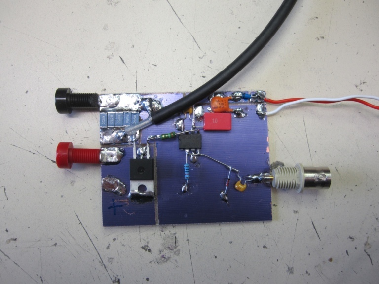
It need only a small 15v supply. A BNC cable connected to the shunt allow to monitor the short circuit current. Two 4mm female bananas are used to connected the output of the PSU you want to test.
To finish, the female BNC receive the input pulse from an external generator.
To avoid too long driving pulse and protect the Mosfet, a CR derivator limit the drive pulse to few tens of µs.
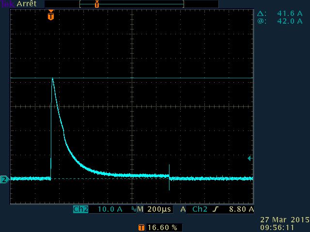
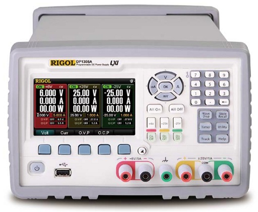
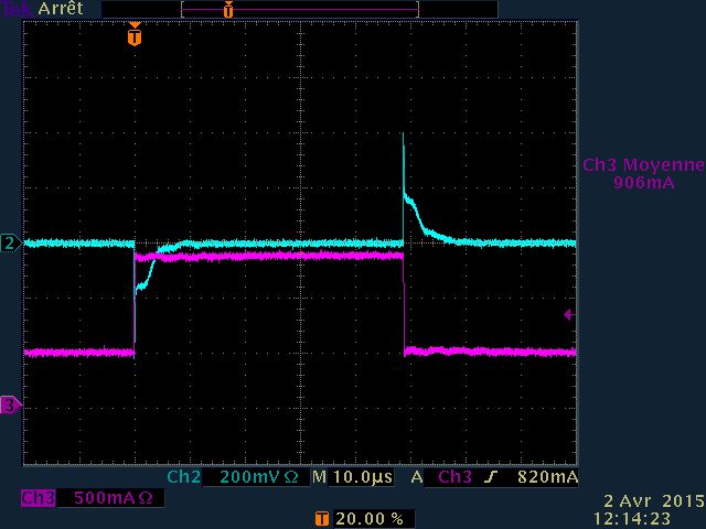
You can see below the short circuit of a DP1308 RIGOL Lab PSU compared
to the EPSUX3REGv1 board in same conditions;
DP1308A (12V 1A set) :
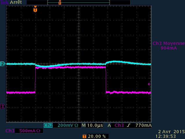
EPSUX3REGv1 (12 1A set)
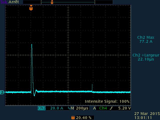
As you can see and despite that the DP1308 work very well, the EPSUX3REGv1 board have current regulation recovery much faster (about 50µs).
We can see also that the peak over-current measured with EPSUX3REGv1 is 77A and only 43A with the DP1308A.
The higher current value is caused by lower impedance path and very low ESR of output capacitors.
For transient load test, between two current values, i use a Jim Williams design (him again !) describe in application note AN104 from LinearTech.
This design allow more than just makes load test between two value, but allow to test the output of PSU with any current waveforms.
You can see my personal build of this below ;
Front
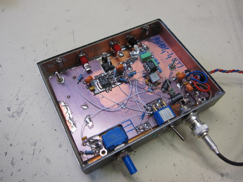
Rear
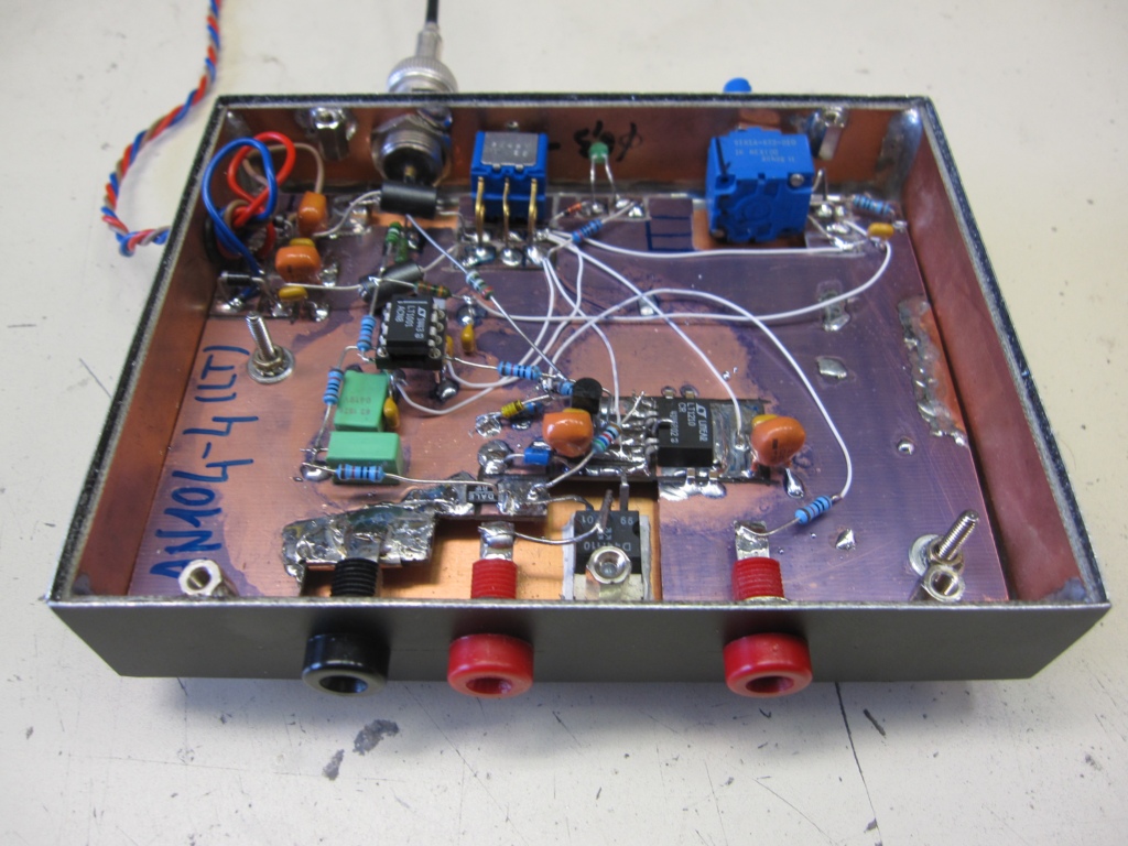
The load tester work as an linear high bandwidth voltage to current amplifier.
It include a potentiometer to adjust the offset current, and a BNC connector allows the connexions of a signal generator with a sensitivity of 1V/A.
Any waveform can be injected, allowing various tests.
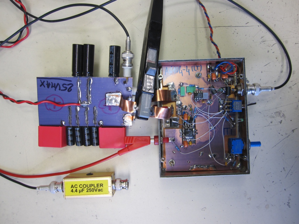
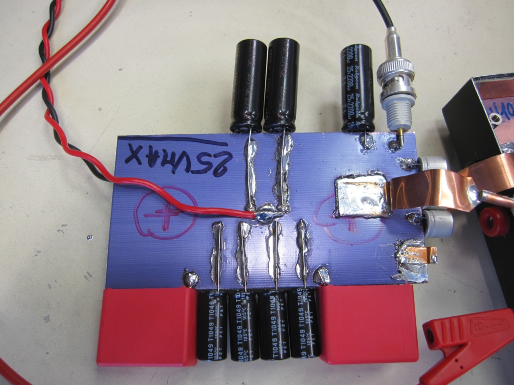
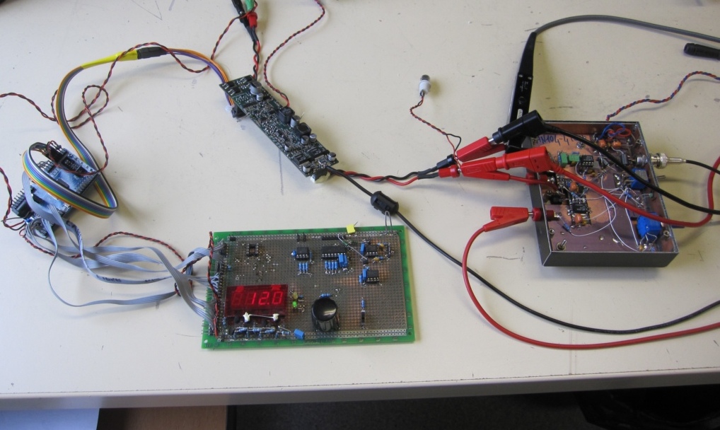
Before to use the load tester, and as recommended in AppNote, i've checked the output current pulse fidelity with ultra low impedance voltage source and a fast current probe.
The test setup and load test are show below :
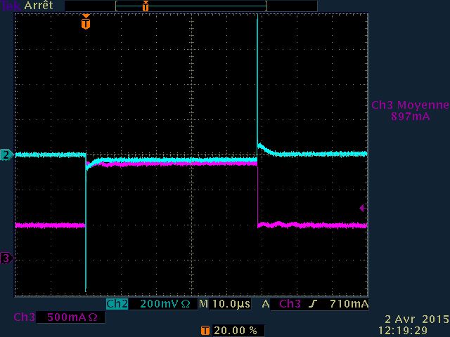
The resulting screenshoot of the output current ;
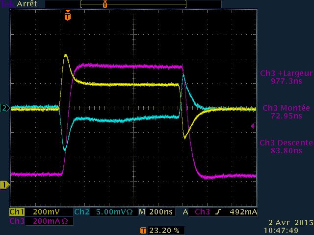
In this case, the offset current is set to 1A, and the step current to 1A for 1µs.
This test is made with pulse generator at input, and allow to see the response time and output signal conformance.
After these checks, i used the load tester with three PSU.
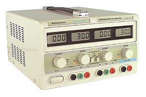
- A low cost lab PSU (Selectronic...)
- A RIGOL DP1308A
- The EPSUX3REGV1 prototype board of course !
Each of them has been tested using same settings :
12V output ,1A continuous current, + 1A 100µs pulse current.
Lead wires between PSU output and load tester <10cm (must be as short as possible to avoid loop inductance).
The resulting measurements :
Selectronic SL1731SB
RIGOL DP1308A
EPSUX3REGV1
EPSUX3REGV1 vertical zoomed view :
As we can see, the transient response behavior of the EPSUX3REGV1 regulator board is excellent and outclass many commercial PSU (peak transient is smother and 10 time lower than DP1308, and 20 time lower than the Selectronic PSU !).
The current limiting functionality work also very well, with extremely fast recovery for effective load protection.
I post all these tests that are not yet completely finished, to clearly show that the design is in progress and that i work hard to finalize a serious design.
I think we all love reading news...
I'll do many others tests with this tool soon. I plan too to make noise measurements and capacitive loading tests.
I would continue to inform you regularly about advancement...
Regards.
Frex
Since my last post, i have done some job on the combo regulator board (EPSUX3REGv1) performance measurements.
I wanted to done serious transient load tests, output current regulation recovery time and short circuit behavior. To do that, i finally decided to build two dedicated tools.
The first one is a simple MOSFET short circuit board with shunt measurement and logic gate driver. This simple tool and a pulse generator allow to make short-circuits current measurements.
This small test board looks like this ;
It need only a small 15v supply. A BNC cable connected to the shunt allow to monitor the short circuit current. Two 4mm female bananas are used to connected the output of the PSU you want to test.
To finish, the female BNC receive the input pulse from an external generator.
To avoid too long driving pulse and protect the Mosfet, a CR derivator limit the drive pulse to few tens of µs.
You can see below the short circuit of a DP1308 RIGOL Lab PSU compared
to the EPSUX3REGv1 board in same conditions;
DP1308A (12V 1A set) :
EPSUX3REGv1 (12 1A set)
As you can see and despite that the DP1308 work very well, the EPSUX3REGv1 board have current regulation recovery much faster (about 50µs).
We can see also that the peak over-current measured with EPSUX3REGv1 is 77A and only 43A with the DP1308A.
The higher current value is caused by lower impedance path and very low ESR of output capacitors.
For transient load test, between two current values, i use a Jim Williams design (him again !) describe in application note AN104 from LinearTech.
This design allow more than just makes load test between two value, but allow to test the output of PSU with any current waveforms.
You can see my personal build of this below ;
Front
Rear
The load tester work as an linear high bandwidth voltage to current amplifier.
It include a potentiometer to adjust the offset current, and a BNC connector allows the connexions of a signal generator with a sensitivity of 1V/A.
Any waveform can be injected, allowing various tests.
Before to use the load tester, and as recommended in AppNote, i've checked the output current pulse fidelity with ultra low impedance voltage source and a fast current probe.
The test setup and load test are show below :
The resulting screenshoot of the output current ;
In this case, the offset current is set to 1A, and the step current to 1A for 1µs.
This test is made with pulse generator at input, and allow to see the response time and output signal conformance.
After these checks, i used the load tester with three PSU.
- A low cost lab PSU (Selectronic...)
- A RIGOL DP1308A
- The EPSUX3REGV1 prototype board of course !
Each of them has been tested using same settings :
12V output ,1A continuous current, + 1A 100µs pulse current.
Lead wires between PSU output and load tester <10cm (must be as short as possible to avoid loop inductance).
The resulting measurements :
Selectronic SL1731SB
RIGOL DP1308A
EPSUX3REGV1
EPSUX3REGV1 vertical zoomed view :
As we can see, the transient response behavior of the EPSUX3REGV1 regulator board is excellent and outclass many commercial PSU (peak transient is smother and 10 time lower than DP1308, and 20 time lower than the Selectronic PSU !).
The current limiting functionality work also very well, with extremely fast recovery for effective load protection.
I post all these tests that are not yet completely finished, to clearly show that the design is in progress and that i work hard to finalize a serious design.
I think we all love reading news...
I'll do many others tests with this tool soon. I plan too to make noise measurements and capacitive loading tests.
I would continue to inform you regularly about advancement...
Regards.
Frex

The first one is a simple MOSFET short circuit board with shunt measurement and logic gate driver. This simple tool and a pulse generator allow to make short-circuits current measurements.
This small test board looks like this ;
It need only a small 15v supply. A BNC cable connected to the shunt allow to monitor the short circuit current. Two 4mm female bananas are used to connected the output of the PSU you want to test.
To finish, the female BNC receive the input pulse from an external generator.
To avoid too long driving pulse and protect the Mosfet, a CR derivator limit the drive pulse to few tens of µs.
Nice job! Is it possible to publish schematics?
For transient load test, between two current values, i use a Jim Williams design (him again !) describe in application note AN104 from LinearTech.
This design allow more than just makes load test between two value, but allow to test the output of PSU with any current waveforms.
Frex
Transient load tester looks fabulous. What circuit you are built: from fig.8 (pg.4) or Fig D1 (pg.15)?
Hello,
Prasimix, the schematics of the short circuit tester is very simple, i think we can guess it just with the picture !
If not, you read below it's full schematics with my high-end CAD;
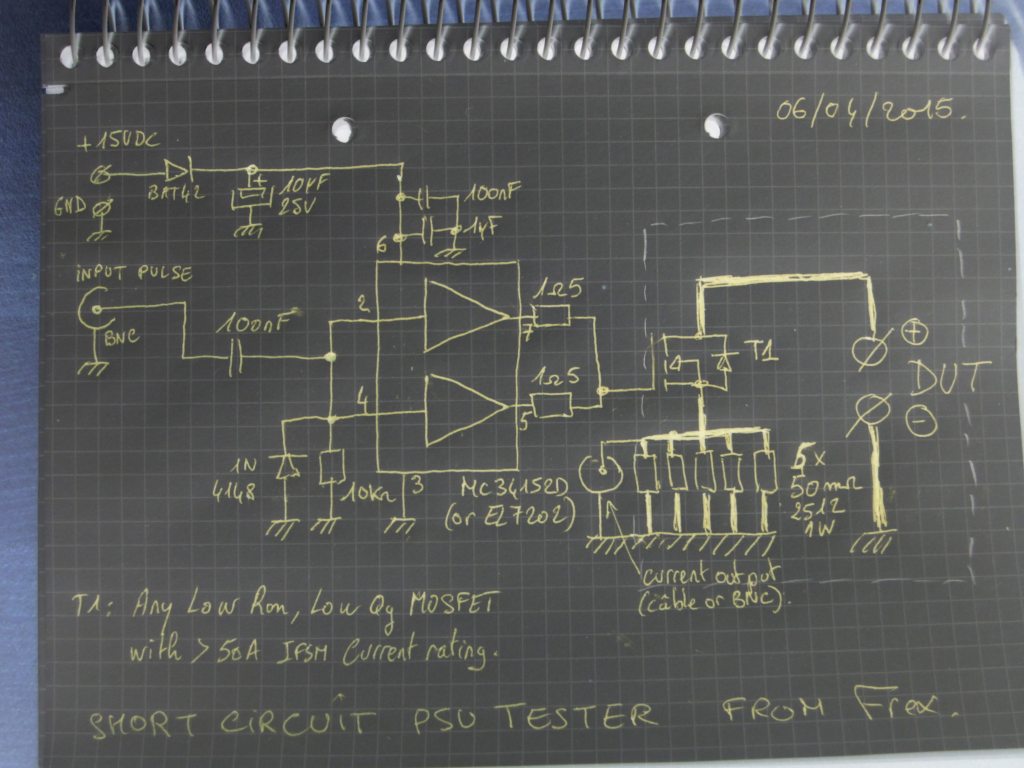
Else, the transient load tester is based on D1 schematics in page 15 of AN104, using no trimming and a bipolar transistor.
Regards.
I just seen that two pictures were missing in my previous post,
it's corrected now (pictures added).
Frex
Prasimix, the schematics of the short circuit tester is very simple, i think we can guess it just with the picture !
If not, you read below it's full schematics with my high-end CAD;
Else, the transient load tester is based on D1 schematics in page 15 of AN104, using no trimming and a bipolar transistor.
Regards.
I just seen that two pictures were missing in my previous post,
it's corrected now (pictures added).
Frex
Last edited:
Thanks Frex! Looking forward for more good news especially about output ripple and noise figures.
Good work Frex 
Based on the level of your design, I was expecting that you have a dedicated programmable DC load to perform all these tests.
It is impressive that you built dedicated testers to test and evaluate this PS design 🙂
Looking forward for the next results.
Based on the level of your design, I was expecting that you have a dedicated programmable DC load to perform all these tests.
It is impressive that you built dedicated testers to test and evaluate this PS design 🙂
Looking forward for the next results.
Hi Frex,
Totally impressing !
And making dedicated measurements tools for just validating a Diy product makes your project in "a different class" by itself
JC
Totally impressing !
And making dedicated measurements tools for just validating a Diy product makes your project in "a different class" by itself
JC
EPSUX3REGv1 output ripple and noise, startup-down measurements
Hello,
I have continued to perform some performance measurements on the EPSUX3REGv1 regulator circuit board.
OUTPUT NOISE TESTS :
Test setup :
Input of EPSUX3 : 25VDC linear bench supply (instead of final LLC).
Output of EPSUX3 : Resistive load with 12V 2A.
Output noise measured with coaxial cable soldered at output, and 4.4uF capacitive coupler with 50 Ohms input scope impedance.
1/ Oscilloscope noise floor.
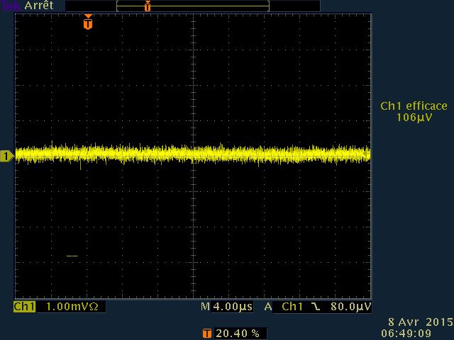
We can show that scope vertical noise floor is about 100µVrms.
2/ EPSUX3REGv1 100MHz bandwidth noise
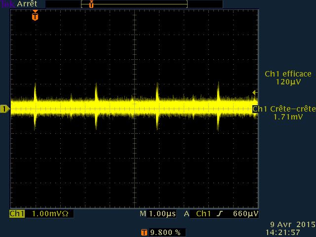
We can show some spike at about 400kHz, that is first stage buck
switching frequency. Their level remains below 2mV peak to peak.
The RMS noise is about 120µV.
3/ EPSUX3REGv1 20MHz bandwidth noise
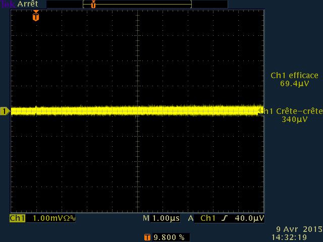
Using only the 20MHz low pass filter of the scope, the swithing spikes
completly dissepear and the broadband noise is 340µV peak to peak
and about 70µV RMS.
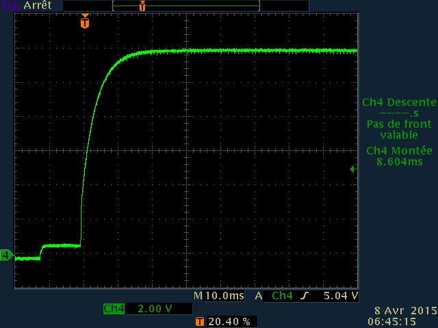
OUTPUT RISE AND FALL TIME WAVEFORMS :
Here we want to see how the output reach the final voltage when enable/disable
switch is used. These tests are performed at 12V output, with and without load.
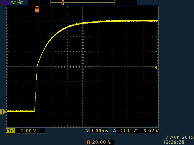
1/ Output rising, 12V No load
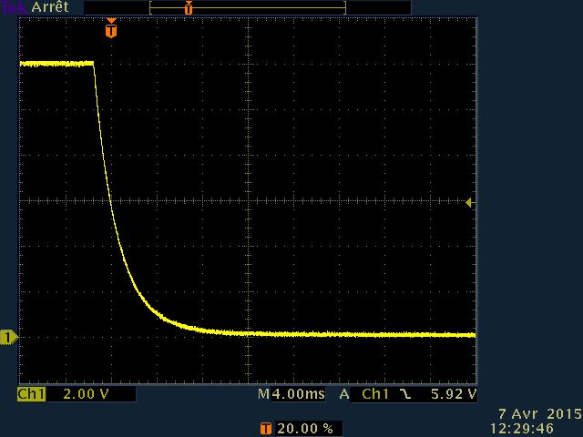
2/ Output falling, 12V No load
3/ Output rising, 12V 2A load
4/ Output falling, 12V 2A load
For now, i'm very happy with all results.
As we show, the start and stop waveforms stay very clean without overshoot.
The combo-regulator circuit board design is effective and i can work to finalize the main board that host three of these. I continue also to work on CPLD software to enhance features.
To be continued...
Hello,
I have continued to perform some performance measurements on the EPSUX3REGv1 regulator circuit board.
OUTPUT NOISE TESTS :
Test setup :
Input of EPSUX3 : 25VDC linear bench supply (instead of final LLC).
Output of EPSUX3 : Resistive load with 12V 2A.
Output noise measured with coaxial cable soldered at output, and 4.4uF capacitive coupler with 50 Ohms input scope impedance.
1/ Oscilloscope noise floor.
We can show that scope vertical noise floor is about 100µVrms.
2/ EPSUX3REGv1 100MHz bandwidth noise
We can show some spike at about 400kHz, that is first stage buck
switching frequency. Their level remains below 2mV peak to peak.
The RMS noise is about 120µV.
3/ EPSUX3REGv1 20MHz bandwidth noise
Using only the 20MHz low pass filter of the scope, the swithing spikes
completly dissepear and the broadband noise is 340µV peak to peak
and about 70µV RMS.
OUTPUT RISE AND FALL TIME WAVEFORMS :
Here we want to see how the output reach the final voltage when enable/disable
switch is used. These tests are performed at 12V output, with and without load.
1/ Output rising, 12V No load
2/ Output falling, 12V No load
3/ Output rising, 12V 2A load
4/ Output falling, 12V 2A load
For now, i'm very happy with all results.
As we show, the start and stop waveforms stay very clean without overshoot.
The combo-regulator circuit board design is effective and i can work to finalize the main board that host three of these. I continue also to work on CPLD software to enhance features.
To be continued...
Using only the 20MHz low pass filter of the scope, the swithing spikes completly dissepear and the broadband noise is 340µV peak to peak
and about 70µV RMS.
Looks fantastic. It seems that you outperform LTC design by at least factor of 10. What you have on the input of pre-regulator while testing? Fully regulated DC or only rectifier with bulk capacitor?
Hello Prasimix,
For these tests, i use a simple 24V/5A regulated linear PSU (2N3055 based). I only want to see buck noise contribution. In final design, this is one of the three LLC outputs that will supply each regulator board. Because LLC waveform are very soft, i hope that output noise figure will not be significantly degraded. I will test that soon.
To get better switching noise rejection, i use very low impedance path and massive ground plane. A second LC filter has been also added between the buck converter and the linear regulators to improve noise suppression.
You can read published schematic of EPSUX3REGv1 for more infos.
Regards.
Frex
Last edited:
Excellent results Frex.
It looks that you will end up with a very high level piece of equipment.
It looks that you will end up with a very high level piece of equipment.
Hello Prasimix,
If you don't have fast (and expensive) current probe, you can use the 0.1R shunt. The current value is not exactly the same because you measure also the base current of the bipolar output transistor (D44H10). It is generally not problematic.
For a proper connexion, you must use coaxial cable soldered the nearest possible on the shunt terminations, without wire loop. You must also use a 50 Ohms plug at oscilloscope input.
About current consumption of the test setup, i 'dont have measured it but it few hundred of mA.
Regards.
FRex
Hello Prasimix,
If you don't have fast (and expensive) current probe, you can use the 0.1R shunt. The current value is not exactly the same because you measure also the base current of the bipolar output transistor (D44H10). It is generally not problematic.
For a proper connexion, you must use coaxial cable soldered the nearest possible on the shunt terminations, without wire loop. You must also use a 50 Ohms plug at oscilloscope input.
Good, I presume that here is more important to get a shape then a value of the current.
Ok, then LM317/337 with small heatsink should be enough (powered from 2x15VAC 4VA transformer).About current consumption of the test setup, i 'dont have measured it but it few hundred of mA.
AN104-15 question
Hi Frex, I have one more question regarding transient load tester from AN104-15: when you conducted testing where minus/gnd terminal of PSU module was connected: to Rsense (blue line) or to the tester ground (red line)?
I presume that you have two load: Rlo that draw Ioff when switch is off and Rhi that in combination with Rlo draw Ion.
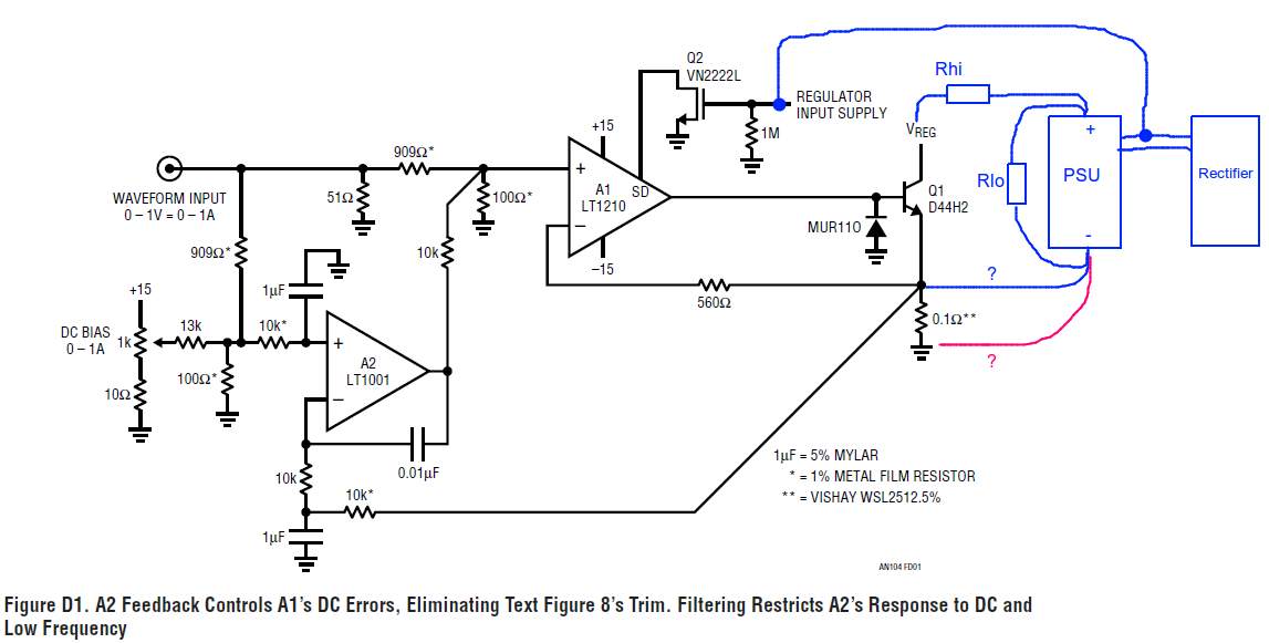
Attachments

Hi Frex, I have one more question regarding transient load tester from AN104-15: when you conducted testing where minus/gnd terminal of PSU module was connected: to Rsense (blue line) or to the tester ground (red line)?
I presume that you have two load: Rlo that draw Ioff when switch is off and Rhi that in combination with Rlo draw Ion.
Huh, it seems that I was pretty tired yesterday to ask such obvious question 😱. It should be red line otherwise current cannot be sensed on Rsense. Sorry.
- Home
- Design & Build
- Equipment & Tools
- Triple outputs 160W Lab PSU -- EPSUX3 version 2 !