Frex, not to go in detail but with fairly spaced ( like 10-20 layers of insulatin tape ,or 1-2 mm space filling the entire winding window with insulation tape and copper ) it is easy to reach leakage concentric windings it is easy to get leakage inductance equal or close to separated windings. Couple capacitance is low.
Most important is that you can do with few layers for each winding , often one if using a long core and therefore wont need litz. Litz or normal wire has similar resistance up to quite high penetration frequncey due to skin depth, normal wire had higher resistance due to this but litz has poor filling, ie a lot of air inside the cable making it occupy space. And litz is a pain to solder. One thread astray and you could short out all!
One wiew of course,your design is very thorough ad the results show!
Hello,
If you search how to control the voltage of the pre-regulator, did you have read the
LT article on which my design is based ?
Frex
Yes, indeed 🙂. Hope it works well in your case. I already sent to the manufacturer PCB layout with a more complex tracker but as you said it makes sense to build a small board for testing what I'll probably do for the both LTC's solutions.
Hello rikkitikkitavi,
I suppose that you have done some tests with your concentric windings if you say that you can get right leakage value.
Probably a planar core, where the geometry allow only few turns and flat copper clad or wide circuit board track can replace advantageously a Litz wire.
So, in my own experience, you need to work at higher frequency than 120kHz if you work with planar and if you want to switch high voltage from main (400V from PFC).
Using lower voltage is easiest.
You can look Payton that made very good custom made planar transformer for any output power.
Regards.
Frex
Hi Frex,
as I can see you are going to run all three pre-regulators with the same frequency. Since it's is only theoretically possible with equal resistors did you consider synchronization between them since TPS54540 has such possibility? That could improve EMI figures and avoid possible generation of "beat noise". Isolation between channels shouldn't be a problem using devices such as Si8610.
as I can see you are going to run all three pre-regulators with the same frequency. Since it's is only theoretically possible with equal resistors did you consider synchronization between them since TPS54540 has such possibility? That could improve EMI figures and avoid possible generation of "beat noise". Isolation between channels shouldn't be a problem using devices such as Si8610.
Frex, my aim was never to be fully integrate the resonance inductance into the transformer using concentric windings as I didnt think that was possible.
Actually I would like to use a small external inductor to trim this inductance to teh correct value, or fairly close. Fex if I needed a resonance inductance in the range of 100 uH I managed to reach about 70 uH leakage inductance when the gap was adjusted to about 800 uH on a RM 14 core.
I agree with your conclusions for the planar core.
I did build a prototype 12V => +-45V push pull with a planar core and some copper foil , but it operated at about 50 kHz.
Hello,
prasimax, synchronizing buck regulators is not necessarily a good thing.
This can be good if you can drive in opposite phase two switching loops to
try cancel them. But, it's not easy particularly at high frequency.
In many case, it's better to choose different switching frequency for each channel to avoid overlap
(because that can increase the EMI level et this particular frequency).
In other case, where we can, we add some random jitter to switching frequency.
It's the spread spectrum technique. Because when EMI level is measured with a spectrum analyzer,
the quasi peak filter see the average level of emission.
When you add jitter the fundamental switching frequency become wider but has lower quasi-peak level !
In my particular case, i will choose slightly different frequency for each channels(no cost!).
Carsten witt, thank you for your comment 🙂.
rikkitikkitavi,
Do you have a good reason to work at so low frequency of 50kHz ?
You could reduce drastically the number of turns and the volume of ferrite core by increasing it.
Regards.
Frex
(Sorry for language mistakes...)
Frex, mostly because I didnt want to have to much losses in the semiconductors, ie the switches. the I^2*Rdson + switching loss was a lot, and as I had a few parallelled SMD mosfets I needed a lot of gate drive current to get a fast switching and lower loss.
In the end I realised I should have done a lot differently 🙂
Perhaps a much stronger driver, or better mosfets...double frequency atleast.
I used two core pairs to get enough cross section. But i think that in the end MLT* turns resistive loss is constant, with constant frequency
In the end I realised I should have done a lot differently 🙂
Perhaps a much stronger driver, or better mosfets...double frequency atleast.
I used two core pairs to get enough cross section. But i think that in the end MLT* turns resistive loss is constant, with constant frequency
Hello,
Some news of the project.
I've received some parts of the PSU that i needed to be sure
of my mechanical drawings.
You can see them on the picture below ;
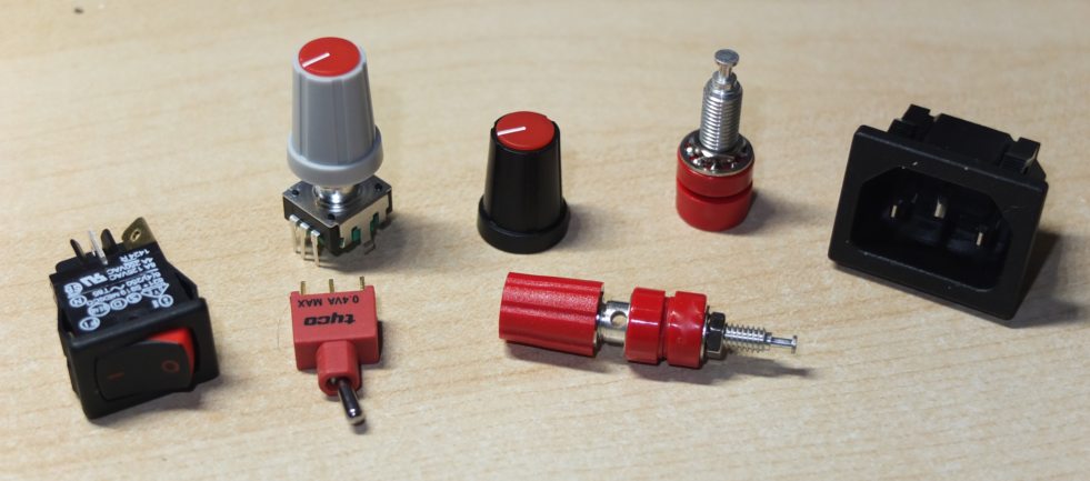
CEE main plug, rotary digital encoder with two knob (i prefer the grey),
the toggle switches, the female bananas jack.
After importing all components in the PCB design CAD software, and after trying to place main parts,
i was aware about lack of space to route conscientiously.
That maybe could be done in routing to both side, but that didn't please me.
After some reflexion, i decided to split the design, with three same boards for the full combo regulator,
and a "motherboard" with the main power supply (PFC/LLC), and all logical functions.
Each of theses three regulator circuit boards will be vertically plugged in the motherboards.
By this mean, the equivalent routing surface is much higher and routing become also much easier.
This approach allows some other benefits ;
- Better heat dissipation (more surface)
- Lower cost for regulators board because x3 quantity !
Of course, that also have some disadvantages, the PCB tooling cost must be paid two times
(2 circuits instead of one), and the mechanical integration is more complicated.
I already spited the schematics on motherboard and regulator board,
and the routing of the prototype combo regulator board is nearly finished.
That actually seem to that below :
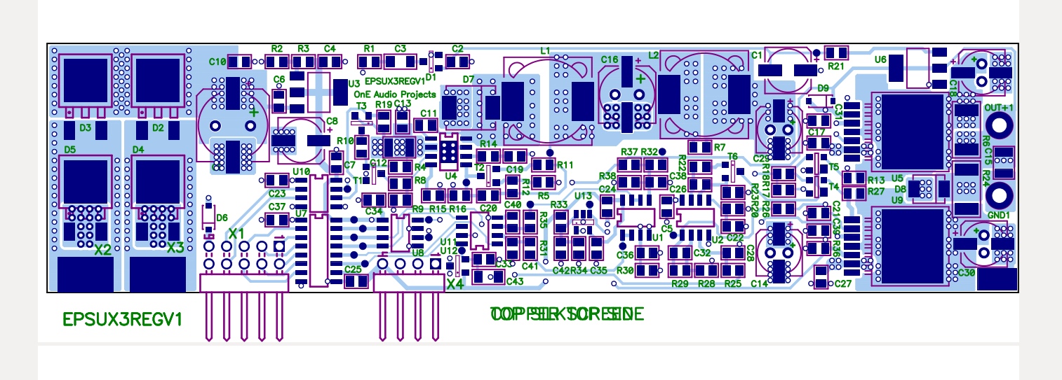
You can download the new schematic of the combo circuit board below ;
EPSUX3REGV1_sch.pdf Combo regulator circuit board schematics (same for the three boards).
I make many checks on it's design at this time, but the PCB will be ordered to WEdirekt in the next week.
This will allow to check very in depth the performance of the combo regulator.
To follow....
Frex
Some news of the project.
I've received some parts of the PSU that i needed to be sure
of my mechanical drawings.
You can see them on the picture below ;
CEE main plug, rotary digital encoder with two knob (i prefer the grey),
the toggle switches, the female bananas jack.
After importing all components in the PCB design CAD software, and after trying to place main parts,
i was aware about lack of space to route conscientiously.
That maybe could be done in routing to both side, but that didn't please me.
After some reflexion, i decided to split the design, with three same boards for the full combo regulator,
and a "motherboard" with the main power supply (PFC/LLC), and all logical functions.
Each of theses three regulator circuit boards will be vertically plugged in the motherboards.
By this mean, the equivalent routing surface is much higher and routing become also much easier.
This approach allows some other benefits ;
- Better heat dissipation (more surface)
- Lower cost for regulators board because x3 quantity !
Of course, that also have some disadvantages, the PCB tooling cost must be paid two times
(2 circuits instead of one), and the mechanical integration is more complicated.
I already spited the schematics on motherboard and regulator board,
and the routing of the prototype combo regulator board is nearly finished.
That actually seem to that below :
You can download the new schematic of the combo circuit board below ;
EPSUX3REGV1_sch.pdf Combo regulator circuit board schematics (same for the three boards).
I make many checks on it's design at this time, but the PCB will be ordered to WEdirekt in the next week.
This will allow to check very in depth the performance of the combo regulator.
To follow....
Frex
Motherboard concept ...
Good job Frex! A motherboard concept is something that I'm have on my mind almost from the beginning. You already mentioned some advantages. On top of that I'd like to say that it makes a whole system a more modular and "future proof" 🙂 since it's not necessary to build everything from the scratch. There is a couple of disadvantages: additional connectors and mechanical fixation of the modules.
Good job Frex! A motherboard concept is something that I'm have on my mind almost from the beginning. You already mentioned some advantages. On top of that I'd like to say that it makes a whole system a more modular and "future proof" 🙂 since it's not necessary to build everything from the scratch. There is a couple of disadvantages: additional connectors and mechanical fixation of the modules.
Hello,
I spent a lot of time this week to route the main circuit board that include the off-line smps, logic and host the three regulator boards.
After trying to integrate regulator circuits boards in the mother board design,
then i had seen that the placement with all parts was not satisfactory.
Because of that, i have made some modification on regulator boards.
The main difference is that now, they will be horizontally mounted.
Each of these boards could be plugged in the mother board without any solder (male/female header).
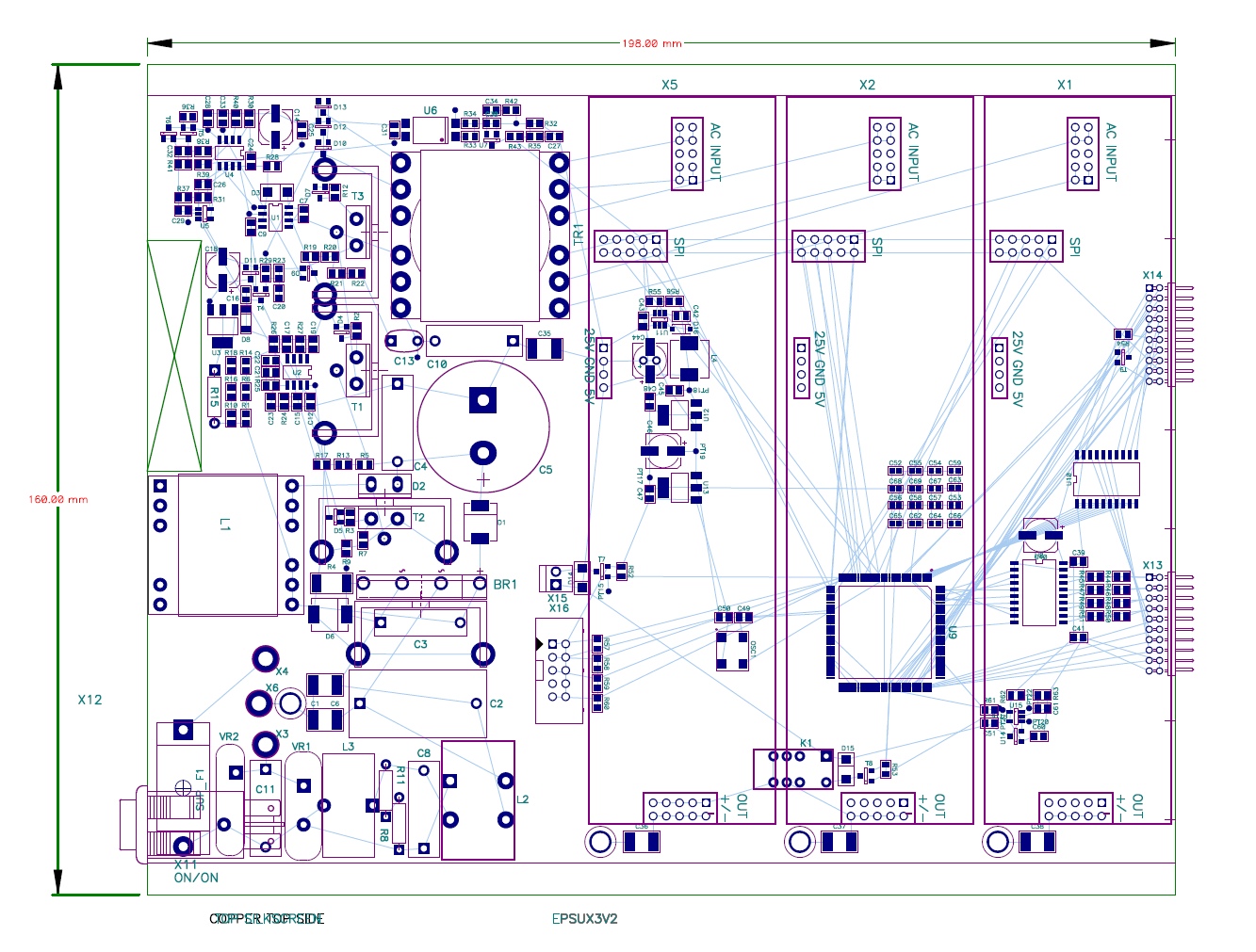
The routing area in the main board is now better distributed and i have already placed essentially all the off line smps parts.
That show actually like this :
The regulator board ordered will look like this :
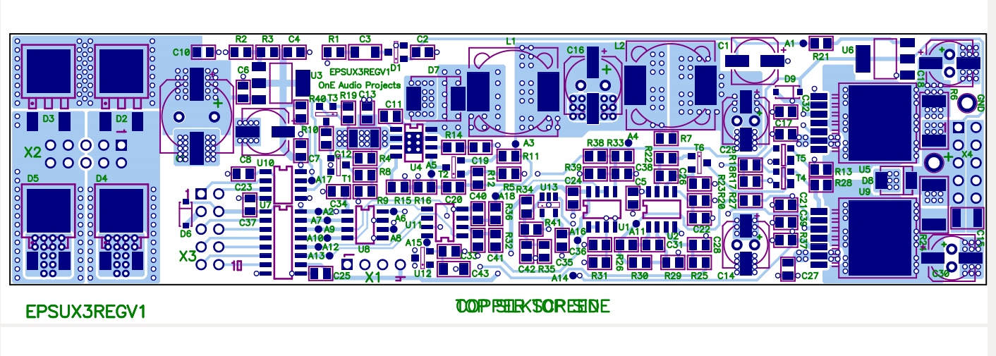
I've ordered this Friday the first three prototypes board of the combo regulator
from Würth Direkt, and i will receive them at end of February.
before to receive the circuits, i continue to work on the main board and mechanical
integration with the front panel board and many others thing.
To follow...
Frex
I spent a lot of time this week to route the main circuit board that include the off-line smps, logic and host the three regulator boards.
After trying to integrate regulator circuits boards in the mother board design,
then i had seen that the placement with all parts was not satisfactory.
Because of that, i have made some modification on regulator boards.
The main difference is that now, they will be horizontally mounted.
Each of these boards could be plugged in the mother board without any solder (male/female header).
The routing area in the main board is now better distributed and i have already placed essentially all the off line smps parts.
That show actually like this :
The regulator board ordered will look like this :
I've ordered this Friday the first three prototypes board of the combo regulator
from Würth Direkt, and i will receive them at end of February.
before to receive the circuits, i continue to work on the main board and mechanical
integration with the front panel board and many others thing.
To follow...
Frex
Hi Frex,
Impressive, I dare to see the final proto working ! I hope that the air flow will be enough in the worst case though
JC
Impressive, I dare to see the final proto working ! I hope that the air flow will be enough in the worst case though
JC
Progression...
Hello,
To complete my previous post, you can look below the new splited schematics of the EPSUX3v2 project.
It include the main board schematic ; EPSUX3V2A_sch.pdf
and the combo regulator board replicated three time ; EPSUX3REGV1A_sch.pdf
I progress to ordering all parts needed to wire the first three combo circuits boards i will receive next week.
I prepare too a test fixture to use the combo regulator alone
with only a CPLD "on the fly" board.
Frex
Great and fast progress 😉
Your pcb design skills are remarkable! Looking forward for the next results based on these pcbs.
BTW, could a regulator pcb stand alone?

Your pcb design skills are remarkable! Looking forward for the next results based on these pcbs.
BTW, could a regulator pcb stand alone?
Hello Spirtos,
Thank you for you interest on the project.
The regulator board can be used without the main-board, but you will need to drive the isolated SPI link to set and read V and I.
Any small MCU board can be used to do that (Arduino...).
You also need to supply the input of the regulator with 25Vdc 2.5A.
Take a look to the EPSUX3REGv1 schematic.
Regards.
This morning, i have ordered to Mouser all missing parts to build the first set of three combo regulator board, and the first main board.
I've prepared some test wires for the combo boards that arrive next week.
I must prepare now a test software to drive the board with my EPM570 breadboard.
Frex
Combo regulator board PCB arrived !
Hello,
I've just received today the circuit boards from WEdirekt, they look like this :
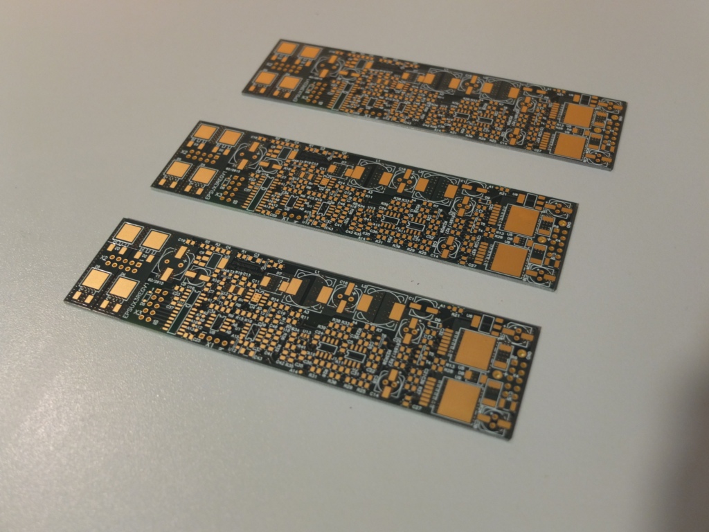
All missing parts arrive this Friday from Mouser, but i can start to solder some parts tomorrow,
like the buck IC that need to be reflow soldered.
To follow... 🙂
Frex
Hello,
I've just received today the circuit boards from WEdirekt, they look like this :
All missing parts arrive this Friday from Mouser, but i can start to solder some parts tomorrow,
like the buck IC that need to be reflow soldered.
To follow... 🙂
Frex
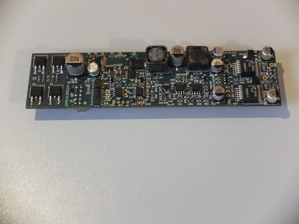
First regulator PCB wired.
Hello all,
After some hours of work, and all missing parts received yesterday, i finally fully wired the first combo-regulator PCB ! Cool !
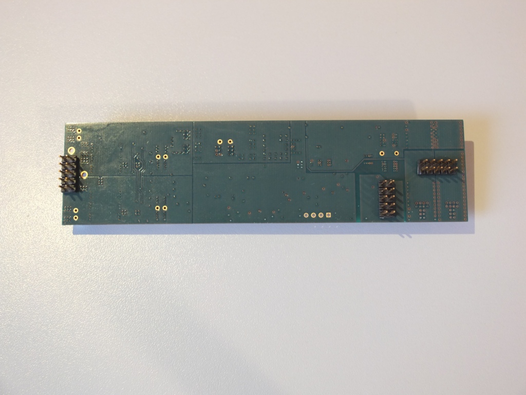
Two small pictures to show you what it looks;
TOP VIEW:
BOTTOM VIEW:
Next step, probably my favorite one : test .
Unfortunately, I will not do that this week-end, too busy by others DIY at home... 🙂
I hope to find in next week the time to power-on the board and check that all is ok.
After that, connecting it to the CPLD board and trying to set voltage/current and reading also V/I.
So, after these functional tests done, i must made extended tests it with various load conditions.
Much work in perspective, but the final target never been closer.
The following very soon...
Frex.
Hello all,
After some hours of work, and all missing parts received yesterday, i finally fully wired the first combo-regulator PCB ! Cool !
Two small pictures to show you what it looks;
TOP VIEW:
BOTTOM VIEW:
Next step, probably my favorite one : test .
Unfortunately, I will not do that this week-end, too busy by others DIY at home... 🙂
I hope to find in next week the time to power-on the board and check that all is ok.
After that, connecting it to the CPLD board and trying to set voltage/current and reading also V/I.
So, after these functional tests done, i must made extended tests it with various load conditions.
Much work in perspective, but the final target never been closer.
The following very soon...
Frex.
Hello Spirtos,
Thank you for you interest on the project.
The regulator board can be used without the main-board, but you will need to drive the isolated SPI link to set and read V and I.
Any small MCU board can be used to do that (Arduino...).
You also need to supply the input of the regulator with 25Vdc 2.5A.
Take a look to the EPSUX3REGv1 schematic.
Regards.
Frex
Nice, I 'll keep it as a future project 🙂
Manual work Carpin.
😱 I should need days of work for this 😛
- Home
- Design & Build
- Equipment & Tools
- Triple outputs 160W Lab PSU -- EPSUX3 version 2 !