Dunno............
......... Probably just being a bit daft - measurements and listening will tell, though!!
Cheers
Jon
......... Probably just being a bit daft - measurements and listening will tell, though!!
Cheers
Jon
SWEET!
you won't be getting any voltage dips/sags with that monster😀 you can't beat an overkill supply
you won't be getting any voltage dips/sags with that monster😀 you can't beat an overkill supply
I don't know if it will do, in fact I think is doesn't. I have gone the same route back in the 80's, the bigger is better. well it ain't I can tell. I have made several power supplies with these kind of big value caps and they sounded all quite terrible. I'm sorry to say but I doubt the quality of those caps and remember qaulity is much more important than quantity. Please try the smps supply with and without those caps.
When I said overkill I just didn't mean overkill as in big😉 I know what you mean though.
I've tried dozens of psu caps (mainly in my UCD's) with mono amps using transformers I settled on 10,000uf T-nets per rail but when trying a SMPS with my Amp6 I liked higher capacitance on the output so its best to try this stuff out, he can easily reduce the UF if he needs to
I've tried dozens of psu caps (mainly in my UCD's) with mono amps using transformers I settled on 10,000uf T-nets per rail but when trying a SMPS with my Amp6 I liked higher capacitance on the output so its best to try this stuff out, he can easily reduce the UF if he needs to
I couldn't agree more!! I'll post results when I get some measurements. I hope the caps are OK, though. This was a GP some time ago for my AX and I wouldn't want to go too cheap with that build - when it happens - next decade etc...... 😉
Cheers
Jon
Cheers
Jon
Is it possible to bridge the ta 10.1 and if its possible how much will the power increase?
And how do i bridge it?
And how do i bridge it?
No it's not possible, it's allready bridged by itself. If it wasn't it would only have a power output of about 2W in 8Ohm from a single 12V supply. If you want more power you'll have to look somewhere else I'm afraid.
when you try to bridge the Tripath amp you will end up with basicly the same amp as before bridging, nothing chances in output power. The chance is it will only work worse than with no bridging.
Just imagine what happens when bridging an amp. You'll apply a signal to the left input and a reversed signal to the right input. Now the two outputs are out of phase so the voltage potential between the two + terminals is doubled compared to the voltage between one of the + terminal and ground. BUT, the voltage doubling is ONLY there when both channels share the common (-) connection and this is NOT the case with the Tripath amps. The negative output connections are also 180 degree out of phase so there will be the same voltage potential between them as there is between the positive terminal. In order to get a fully bridged amp these should be connected to each other but I think it's not so hard to imagine what will happen the, kaboom end of life for the amp within a split second.
I have looked at the forum you refered to and all I see there is a lot of people asking how to bridge the Trends but there is no direct answer from anybody.
I'll stick to the point that it is not possible unless you will use something like a (1+1):1 output transformer. In that case you will have complete galvanci isolation between the two outputs while they still provide there power together into one load. But anyways, bridging the amp is a very atractive idea so I wouldn't mind to be proven wrong in this matter.
Hi,
I found this modder (Maurarte) from Italy, with some very good ideas about mods of input path, input caps, power supply, volume pot (alps), etc.
http://www.maurarte.com/T-AMP.htm
I shipped mine for the mods and will let you know when it comes back !
All the best
Alessandro Fogar
I found this modder (Maurarte) from Italy, with some very good ideas about mods of input path, input caps, power supply, volume pot (alps), etc.
http://www.maurarte.com/T-AMP.htm
I shipped mine for the mods and will let you know when it comes back !
All the best
Alessandro Fogar
That looks a lot like how i did the rewiring of the power supply and the input circuit with the only difference that I skipped the volume pot to make it a poweramp only.
The problem with the standard configuration lies mainly in the groundpath. The powersupply and the inputsignal are both grounded on the groundplane right at the input of the amp. This means that the power supply current, the inputsignal current and the outputfilter currents are somehow randomly connected to the groundplane so the currents are flowing trough eachother like crazy, not a good thing. Bringing the power supply ground directly to the power supply caps reduces a lot of these currents. The input goround shuld be connected as close to the analog ground pin of the chip as posible, not "wide open" on the ground plane. This little trick will cost you next to nothing and is the best trick to get rid of the hissssss and harh treble, I really consider it a must do to make the amp listenable.
As you all will see, I didn't give up on the Trends yet, it's still not better then my other amps but at least I can listen to it now, with the stock amp this was very terrible, it's a pretty bad pcb layout if you ak me.
well I think the pictures from the mentioned italian website speak for themselves. Main issue is to connect the incoming ground connections from both the power supply and the signal as close as possble to the place where the actual currents flow. that is right at the reservoir caps and right at the input of the chip, that's it.
In the pictures on the website I see that the input ground is still directly connected to the goundplane, it works much better by disconnecting this and connect the ground at the chipside. this way the input currents don't get screwed up by the powersupply and outputfilter currents wich are mainly high frequent components.
I have used a shielded cable and soldered it direct from the input to the coupling caps and after that directly to gain setting resistors of the input circuit.
An externally hosted image should be here but it was not working when we last tested it.
I'm curious about this picture. It looks like the wires short themselves. I don't see how the ground of the caps are attached to the wire, or where the wire is attached.
Re: Preamp?
Hi All,
Sorry, I need to make a correction here: This image and indeed excellent info was found originally on the WAD forum.
http://wduk.worldomain.net/forum/showthread.php?t=198
Cheers
Jon
jonclancy said:If you want a budget solution that sings, try a shunt modded ALPS Blue. My 50K pot is shunted with Dale RN55s and then parallelled with a (same make) resistor network to get 25K (for more volume). It's cheaper than most solutions and sounds great!
Thanks to the guys on PFM for the pic - it's not mine.
Jon
Hi All,
Sorry, I need to make a correction here: This image and indeed excellent info was found originally on the WAD forum.
http://wduk.worldomain.net/forum/showthread.php?t=198
Cheers
Jon
Originally posted by dweekie It looks like the wires short themselves. I don't see how the ground of the caps are attached to the wire, or where the wire is attached. [/B]
He's just running the positive wire directly to the tank caps. Then back to a + point on the board were the power connector was. It's the positve sides of the caps "look" shorted, but they are connected by a trace you can't see under the solder.
I used to do a similar mod on the Sonic. Kept the + lead long on the tank cap and used it to jump over to the + input. Makes for a somewhat lower impedence power run. (can't seem to find a photo of the mod - will keep looking).
Shunt Pot Mod
Hi All,
I tried the shunt pot mod on the 100K TA-10 pot today with mixed results. I drilled a couple of extra holes in the front fascia to give me some options with pot orientation. I was going to run separate inputs direct from the RCAs to the (resistors and then) pot, thereafter direct to the jumpers. However, in the interests of a quicker build, I just ran from the jumpers instead.
The thing about a shunt pot is that although the signal has a pretty direct path, the quality of the resistors used and, of course, the vol pot, will influence the final result. I used 10K MRS25 1% metal films which are known to be good quality (my first choice was Vishay Dale RN55 as used in my Alps shunt modded pot, but had none to hand).
I had a bit of a head scratch working out the wiring - seems to be a habit of mine!! 😀 🙄 Suffice to say, the first attempt had the volume pot working "back to front" and getting loud with very little rotation. I flipped the pot around and rewired the other way. OK, so the pot worked in the correct sense but still got very loud very quickly. Hmm - I've got something wrong here.
  Suffice to say, though, that the sound lacked the sparkle or my Alps pot. 30 seconds with the iron later and the mod was removed and it's back to the original power amp config.
Here's a couple of photos - perhaps someone else would like to give it a go? IIRC there is a Panasonic pot that is similar size - is it available at Farnell? Could give that a go. Plan X was fitting the Alps shunt modded pot into a larger case with the TA-10, but it would be a shame not to have a smaller sized case. I still have to investegate whether there are enough CCs available in the TA-10 enclosure to fit the Alps in there, even if it means a new (big) spindle hole in the front face. A new faceplate from the Front Panel Designer outfit might be the way to go here.
But that's for another day - enough DIY now, it's time for a beer!!!

Cheers!!
Jon
Hi All,
I tried the shunt pot mod on the 100K TA-10 pot today with mixed results. I drilled a couple of extra holes in the front fascia to give me some options with pot orientation. I was going to run separate inputs direct from the RCAs to the (resistors and then) pot, thereafter direct to the jumpers. However, in the interests of a quicker build, I just ran from the jumpers instead.
The thing about a shunt pot is that although the signal has a pretty direct path, the quality of the resistors used and, of course, the vol pot, will influence the final result. I used 10K MRS25 1% metal films which are known to be good quality (my first choice was Vishay Dale RN55 as used in my Alps shunt modded pot, but had none to hand).
I had a bit of a head scratch working out the wiring - seems to be a habit of mine!! 😀 🙄 Suffice to say, the first attempt had the volume pot working "back to front" and getting loud with very little rotation. I flipped the pot around and rewired the other way. OK, so the pot worked in the correct sense
but still got very loud very quickly. Hmm - I've got something wrong here. Suffice to say, though, that the sound lacked the sparkle or my Alps pot. 30 seconds with the iron later and the mod was removed and it's back to the original power amp config.Here's a couple of photos - perhaps someone else would like to give it a go? IIRC there is a Panasonic pot that is similar size - is it available at Farnell? Could give that a go. Plan X was fitting the Alps shunt modded pot into a larger case with the TA-10, but it would be a shame not to have a smaller sized case. I still have to investegate whether there are enough CCs available in the TA-10 enclosure to fit the Alps in there, even if it means a new (big) spindle hole in the front face. A new faceplate from the Front Panel Designer outfit might be the way to go here.
But that's for another day - enough DIY now, it's time for a beer!!!
Cheers!!
Jon
Attachments
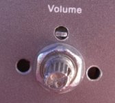
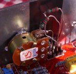
............and the other pic...........
You'll be able to work out the wiring fron this, I hope. Input jumper - resistor - pot - output jumper. The earth is tapped from the small pad in the front corner of the PCB by the pot (left side of pic, just visible behind the trimpot).
Jon
You'll be able to work out the wiring fron this, I hope. Input jumper - resistor - pot - output jumper. The earth is tapped from the small pad in the front corner of the PCB by the pot (left side of pic, just visible behind the trimpot).
Jon
Attachments
- Status
- Not open for further replies.
- Home
- Amplifiers
- Class D
- Trends Audio TA-10: Modding Potential?