It's a good performing & well behaved transistor, first image below. I bought 200 of them (total cost: $13.50) from Mouser: sales link
_
That's a nice transistor with 800mA capability and 600 Hfe. Nice Tek curve tracer. 🙂
I am starting to build the Apex BJT preamp from page 1. Mostly because I like the symmetry of the design and I have lots of BC550/560c's already. Should fit on a tiny 4x6cm veroboard.
Part numbers for the transistors and operating voltage??
This circuit was discussed in http://www.diyaudio.com/forums/solid-state/51141-preamp-schematic-5.html . In 2014, Mooly analyzed this circuit at length.
This circuit was discussed in http://www.diyaudio.com/forums/solid-state/51141-preamp-schematic-5.html . In 2014, Mooly analyzed this circuit at length.
Thanks for the link.
70V seems a little high for a preamp. The ZTX107 transistors are long gone but there are some old stock 2N2905 available on eBay.
I assume different and more readily available transistors can be used with a lower operating voltage?
What transistors and voltage are you using?
Do you by chance have a link to where Mooly analyzed the circuit?
any TO-92 with high FT (100MHz or above) with high gain and can handle 115mW should fit well.Nice design Kroto. Are there any alternatives to the BC337?
Q1 is 2N5401, IMO its sound signature is musical (subjectively, no need to debate). Although the noise figure isn't so good, but maybe that is the reason it sounded good, kinda add dithering to the sound. Something that the OP want, warm fuzzy sound?? 😀
To drive high capacitance, the 100R output resistor is essential, if omitted it will start to show quite high overshot ringing (about 20% with 500pF load).
Or use a lower feedback resistor & Q4 base resistor value to extend the capability.
To drive even more capacitance, use JLH Class-A.
I've built one for headphone amplifier using vintage transistor. Driving 10nF only give about 15% overshot.

Current feedback with Class-A output is awesome 😉
a very typical Indian word, only a few outsiders would know...have you stayed in India, by any chance?jugaad,
Ok, I guess our Friend jrp27 just earned a custom design 🙂

with lots of jugaad, of course 😀
I don´t want to even *imagine* what kind of chassis it might be housed in 🙂
Thanks a ton.for this schematic. How do I make it work for 30 v. What modifications do I need to do i need to do so that it works on 30 volts?
None! Except you can get away with a 35V rating for C2 (rather than 50V). That might save a few paisa.How do I make it work for 30 v. What modifications do I need to do so that it works on 30 volts?
If you study the schematic a little, the transistors actually run on 24 volts (provided by the zener diode and associated components). This will still be true if you supply it with 30v instead of 45 V.
If it will make you feel better, it wouldn't hurt to drop R7 and R8 to 470 ohms (instead of 1 k). This will keep the current through the zener from dropping too much. (Zeners get noisy at very low current.)
-Gnobuddy
Thanks a ton.for this schematic.
once the input level reach 1Vpk, you get a plenty of "warm and fuzzy" a go go
I like it!
🙂once the input level reach 1Vpk, you get plenty of "warm and fuzzy"
There will be roughly 2 volts DC at the emitter of the input transistor, so the circuit copes with up to 2 volts peak (4 Vpp) before actual clipping starts.
I believe there are plenty of CD players that put out a signal that can exceed 2 volts peak. With one of those connected, and a "loud" heavily compressed CD playing, this preamp probably will turn into Jimi Hendrix' fuzz-face. Maybe that's what the OP wants, I don't know. 😀
A simple NE5532 preamp would have far lower distortion, higher input impedance, lower output impedance, better supply noise rejection, and generally be better all around. And it would be much simpler to build, too.

I'm quite sure Mr. Fahey knows all this very well, of course!
-Gnobuddy
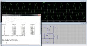
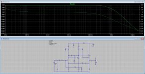
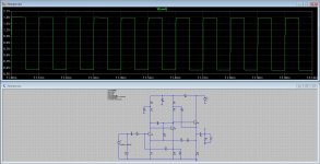
Just for giggles these are the sim results from the circuit I posted earlier. All these are with 1k load (the load I'm driving with it) and the 10k square is with 1nF in parallel.
Attachments

🙂
There will be roughly 2 volts DC at the emitter of the input transistor, so the circuit copes with up to 2 volts peak (4 Vpp) before actual clipping starts.
I believe there are plenty of CD players that put out a signal that can exceed 2 volts peak. With one of those connected, and a "loud" heavily compressed CD playing, this preamp probably will turn into Jimi Hendrix' fuzz-face. Maybe that's what the OP wants, I don't know. 😀
A simple NE5532 preamp would have far lower distortion, higher input impedance, lower output impedance, better supply noise rejection, and generally be better all around. And it would be much simpler to build, too.
I'm quite sure Mr. Fahey knows all this very well, of course!
-Gnobuddy
I already tried using the ne5532 . The sound was muffled and seemed like too much gain was overloading the amp.
The sound was very low and distorted.
Guys, stick with the APEX schematics if you want to make a preamp on your own.
The others are very, very, old fashioned, and not very useful, even if they sometimes can sound OK. They are from the '60's, and we don't use them anymore.
The others are very, very, old fashioned, and not very useful, even if they sometimes can sound OK. They are from the '60's, and we don't use them anymore.
I already tried using the ne5532 . The sound was muffled and seemed like too much gain was overloading the amp.
The sound was very low and distorted.
Instead of making accusations that the NE5532 sounds "muffled" and "the sound was very low and distorted, why don't you post the actual circuit you attempted to use the '5532 in?
If you haven't implemented the chip properly, how can you expect it to work??
The '5532 is easy to use and will certainly sound as good or better than most of these 2 and 3 transistor circuits posted in this thread so far.
Guys, stick with the APEX schematics if you want to make a preamp on your own.
The others are very, very, old fashioned, and not very useful, even if they sometimes can sound OK. They are from the '60's, and we don't use them anymore.
Fully agree, but in this case that´s what the OP is asking for 😉
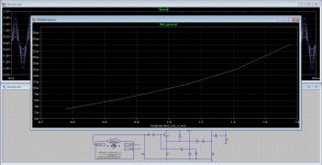
Apex SB 3.1 preamp
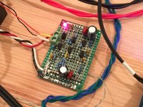
I built one channel of the Apex BJT preamp. 6 transistors and miscellaneous parts make it just as complicated to build as a full blown power amp. 🙂 I am using 100R vs 82R on the output stage resistors and 100pF vs 82pF on the caps. Running 25v rails (same as the M2 amp).
Schematic:
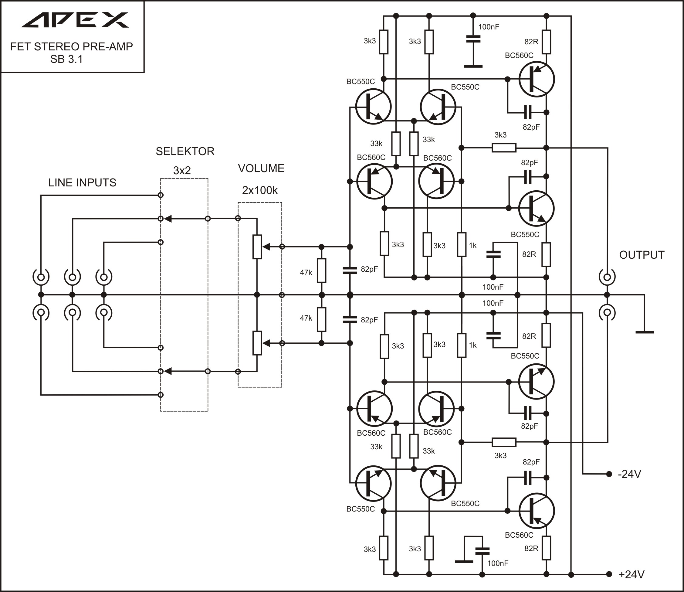
I matched the Hfe's of the transistor pairs of same sex but could not match perfectly NPN and PNP, so this gave me offset of 30mV. It has a lot of drive capability but listening to it, sounded a bit "fuzzy". The gain was nice and put the M2 into the right ballpark for decent volumes from my DAC output.
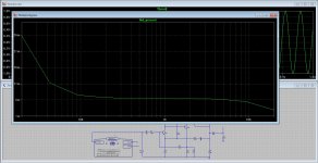
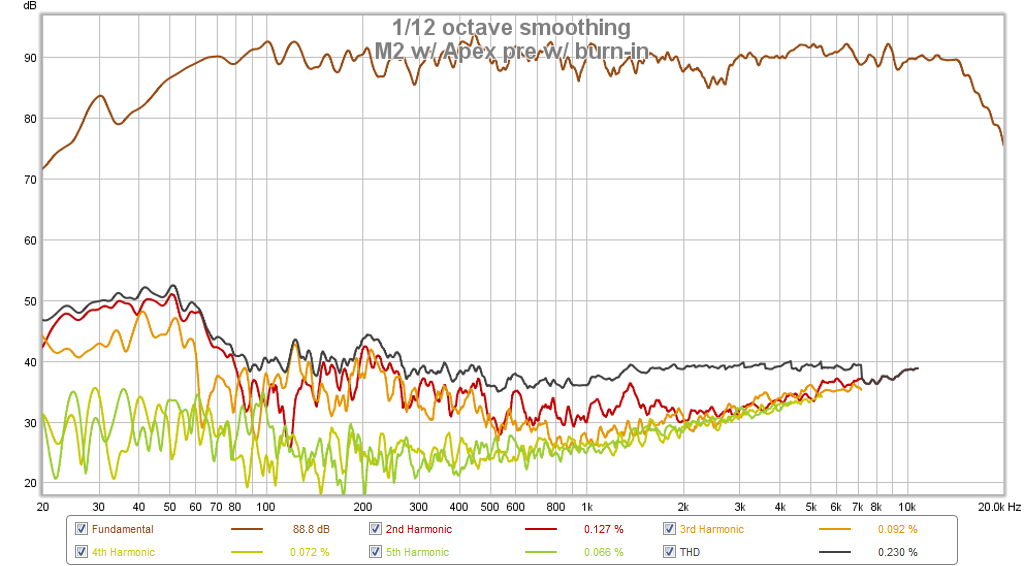
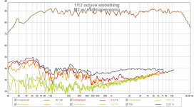
Measurement of the sound from my speakers with my calibrated mic rig showed an increase in distortion vs the 18 channel mixer I was using for a preamp, and most of the distortion was H3. I am not sure why such a simple discrete pre-amp that has similar topology (differential LTP and complementary output) as my Apex power amps would have such high distortion? Maybe veroboard is not as good as PCB?

HD with Apex 3.1 preamp:

HD with midiman 18 channel preamp:

I don't think this is going to work for me, too much distortion.
*** EDIT ***
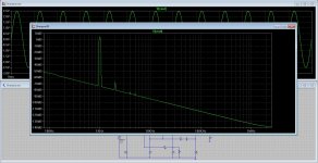
I take back what I said above about the Apex preamp. I just witnessed burn-in before my eyes. After playing for a while, the distortion is just as good as the commercial preamp. I guess I have a good circuit then. Here is measured HD at the speaker with burn in:
I built one channel of the Apex BJT preamp. 6 transistors and miscellaneous parts make it just as complicated to build as a full blown power amp. 🙂 I am using 100R vs 82R on the output stage resistors and 100pF vs 82pF on the caps. Running 25v rails (same as the M2 amp).
Schematic:
I matched the Hfe's of the transistor pairs of same sex but could not match perfectly NPN and PNP, so this gave me offset of 30mV. It has a lot of drive capability but listening to it, sounded a bit "fuzzy". The gain was nice and put the M2 into the right ballpark for decent volumes from my DAC output.
Measurement of the sound from my speakers with my calibrated mic rig showed an increase in distortion vs the 18 channel mixer I was using for a preamp, and most of the distortion was H3. I am not sure why such a simple discrete pre-amp that has similar topology (differential LTP and complementary output) as my Apex power amps would have such high distortion? Maybe veroboard is not as good as PCB?
HD with Apex 3.1 preamp:
HD with midiman 18 channel preamp:
I don't think this is going to work for me, too much distortion.
*** EDIT ***
I take back what I said above about the Apex preamp. I just witnessed burn-in before my eyes. After playing for a while, the distortion is just as good as the commercial preamp. I guess I have a good circuit then. Here is measured HD at the speaker with burn in:
Attachments


Last edited:
Instead of making accusations that the NE5532 sounds "muffled" and "the sound was very low and distorted, why don't you post the actual circuit you attempted to use the '5532 in?
If you haven't implemented the chip properly, how can you expect it to work??
The '5532 is easy to use and will certainly sound as good or better than most of these 2 and 3 transistor circuits posted in this thread so far.
I made the same circuit as mentioned ESP website. Used the same values and same layout. I have attached the layout.
Attachments

Last edited:
I can't see the layout...I made the same circuit as mentioned ESP website. Used the same values and same layout. I have attached the layout.
I can't see the layout...
Attaching it again....
Attachments
I made the same circuit as mentioned ESP website. Used the same values and same layout. I have attached the layout.
That only means there is some issue with either your signal source, or your power amp. This one does not influence the sound by design - at least in the setup, where you're trying to use it.
Good advice from John, fully agree with Ammel.
X, when will you arrange something to measure the amps (not only the speakers)? 😉 The distortion level of the circuit, like the Apex's one, is too low to see in the end of the whole circle, including the speaker, microphone, etc. 😛
- Home
- Source & Line
- Analog Line Level
- Transistor Preamp