OK, i changed the ground wiring slightly. Now i have made the signal ground star on the black Spk out of each channel by connecting the RCA ground here. a Wire connects this star to the channel's pcb, where the 0v rail is connected. This has lowered the hum slighly, but it is still loud enough to be unlistenable...
im all out of ideas so any further suggestions would be very much appreciated 🙂
cheers,
mymindinside
im all out of ideas so any further suggestions would be very much appreciated 🙂
cheers,
mymindinside
Hi Andrew,
i think you posted as i was typing. the cables are secured together. i will try removing one of the shields at one end..
thanks,
mymindinside
i think you posted as i was typing. the cables are secured together. i will try removing one of the shields at one end..
thanks,
mymindinside
Andrew,
It didnt help 🙁, i just got a really loud buzz from the channel that i had removed one shield from.
any other suggestions, did my wiring diagram look ok to you?
what do you think of the fact that the amp is silent with the rca - minplug cable plugged in but starts humming when i plug the ipod in.
thanks to all for the patient help and advice
the RCA miniplug has an outer shield, with two signal cores.what do you think of the fact that the amp is silent with the rca - minplug cable plugged in but starts humming when i plug the ipod in.
If you plug it in and leave the other end open, I would expect some noise on the output of the amplifier.
Hi Andrew,
The amp was silent with the miniplug end open, it started humming as soon as i plugged in the ipod.
the hum i have is quite loud, not the put your ear against the speaker kind.
it fills up the room...
EDIT: with the miniplug cable,these are the possibilities and the resultant hum
1. Both RCAs plugged into the amp but miniplug open - no hum
2. One RCA plugged into the amp and miniplug plugged into ipod headphone out - no hum (both speakers are connected to the amplifier in this case)
3. Both RCAs plugged into the amp and the miniplug plugged into the ipod - loud hum
cheers,
mymindinside
Last edited:
It seems like somewhere in your case the two channels are unintentionally electrically connected.
To be honest I think it might be quicker, to pull everything out of that case and build it again one channel at a time and triple checking everything.
Are you sure there is not another connection to the chassis check all your binding posts, rca's.
Also check ALL of your pcb standoffs.
Build it again.
OK, i changed the ground wiring slightly. Now i have made the signal ground star on the black Spk out of each channel by connecting the RCA ground here.
The speaker-return should be attached to star, not speaker-out.
Is black, speaker-out, or is red, speaker-out?
The conventional wiring is red (for speaker-out) but I think Nelson recommended black to account for phase reversal of amp.
Be careful not to short the amp, it is very easy to make silly mistakes when your patience is wearing thin.
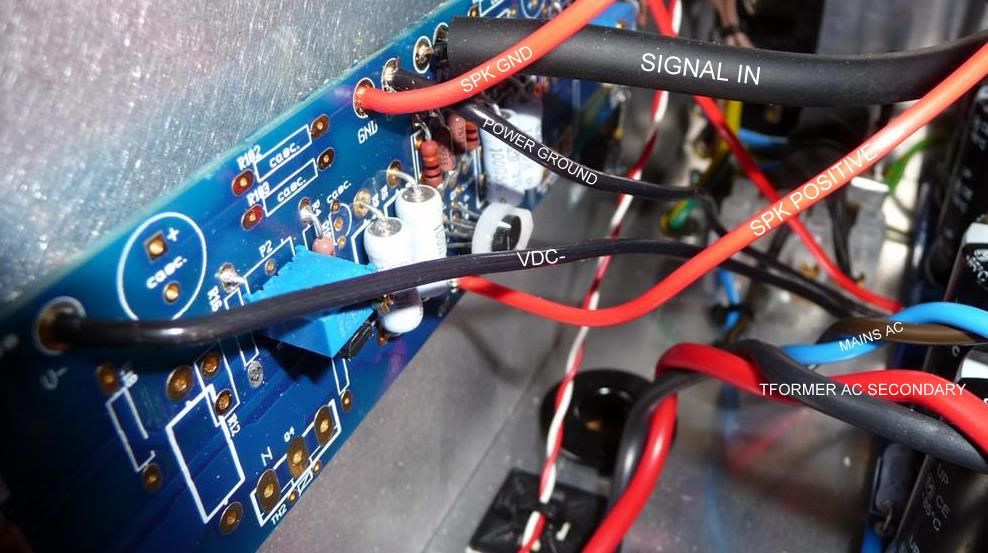
What are those input caps for? I would remove them before trying more fancy solutions. Also the speaker wires could benefit from being twisted. Just make sure you don't have power conducting wires in the loop - right now you have one of the supplies in the speaker loop on the left channel.
What are those input caps for? I would remove them before trying more fancy solutions. Also the speaker wires could benefit from being twisted. Just make sure you don't have power conducting wires in the loop - right now you have one of the supplies in the speaker loop on the left channel.
Hi Christian
If you are referring to my picture, the input caps were added whilst trying to solve the hum problem. I'll remove them for now.
I'm not sure I follow this comment...
'- right now you have one of the supplies in the speaker loop on the left channel'
I've just checked and it appears the right channel is wired the same as the left 😕
Regards
If you look at the left side of the picture, the V- supply is running through the loop of gnd and out.
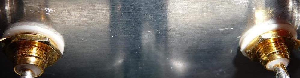
Could you take some pictures of the rca plugs? Sometimes I have used tape to make sure that they are not touching the chassis.
Could you take some pictures of the rca plugs? Sometimes I have used tape to make sure that they are not touching the chassis.
Yes, here you have the vdc- running through the open loop of your speaker cables - it is probably not the root cause, but it is worth fixing.
Are the holes for the RCAs big enough to avoid metal contact? Do you have insulation on the other side as well?
Are the holes for the RCAs big enough to avoid metal contact? Do you have insulation on the other side as well?
If you look at the left side of the picture, the V- supply is running through the loop of gnd and out.
Could you take some pictures of the rca plugs? Sometimes I have used tape to make sure that they are not touching the chassis.
Here you are...
Yes, here you have the vdc- running through the open loop of your speaker cables - it is probably not the root cause, but it is worth fixing.
Are the holes for the RCAs big enough to avoid metal contact? Do you have insulation on the other side as well?
Yes the holes are much larger than the RCAs and they are also insulated on the other side.
Are you recommending I de-solder the current spk ground and the power ground, swap the cables around and re-solder?
Here is the diagram I followed.
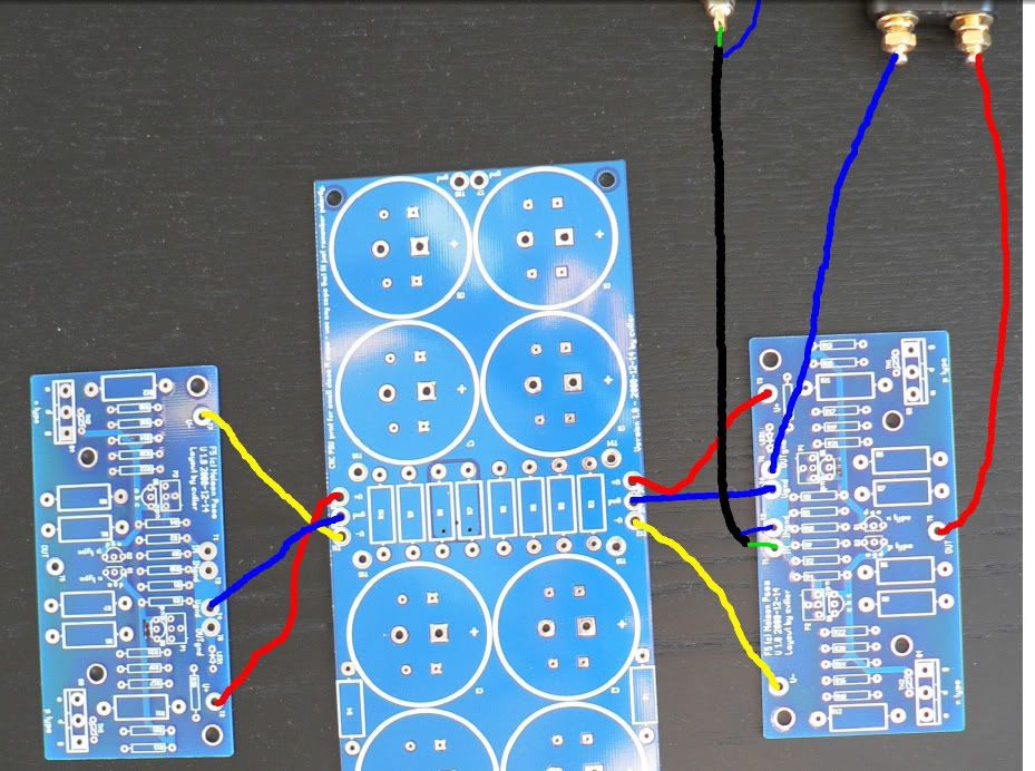
You can just unscrew the v- and run it around the speaker loop. But as I said, this is probably not what fixes your hum issue.
Are you running all your equipment from the same power strip?
Are you running all your equipment from the same power strip?
You can just unscrew the v- and run it around the speaker loop. But as I said, this is probably not what fixes your hum issue.
Are you running all your equipment from the same power strip?
Hello again 🙂
If I disconnect the power from the opposing channel the hum disappears.
Yes they are all running off the same power strip. I'll try and run a separate cable from another wall socket
Same socket should be best. Have you tried breaking the amp gnd and chassis? Do you have hum if you leave the RCAs unconnected?
Same socket should be best. Have you tried breaking the amp gnd and chassis? Do you have hum if you leave the RCAs unconnected?
No hum if I short the RCA.
I have joined the two power supply grounds at the rear of the case and these two wires come together. I then attached a CL60 in series, and connected this via a wire to the safety earth point. I temporarily disconnected the safety earth on the amp and the pre and it did make any difference with regards to hum.
Hi,
the blue and red running to the speaker terminals look like one channel Flow and Return.
These should be twisted together as a pair.
At the chassis terminals maintain the minimum area of loop to reach the terminal soldering points.
At the PCB keep the wires twisted right up to the Flow connection at speaker OUT. Keep the Return wire crossing over or under the PCB and take it to meet up with the power ground. Twist it with the power ground to continue it's route to reach the Main Audio Star Ground.
The PCB has spaced apart supply rails terminations. This is bad layout, but you are stuck with it in this PCB. These must be brought together and twisted with the Power Ground back to the Main Audio Ground Star and then continue past the star as a twisted triplet to the PSU output. Again maintaining the minimum loop area at every termination.
You will have a twisted triplet from PSU to Main Audio Star Ground.
A twisted quad from MASG to amp.
Three single wires at the PCB.
A twisted pair from PCB to speaker Terminals.
This is the best way I can see to minimise the loop areas of the high current cables.
I do not know if it will help, but it is certainly worth trying.
Now back to this two channel problem.
Do you have two MASG? One to each channel, or do you have one MASG shared between the two channels?
Last edited:
Hi,
the blue and red running to the speaker terminals look like one channel Flow and Return.
These should be twisted together as a pair.
At the chassis terminals maintain the minimum area of loop to reach the terminal soldering points.
At the PCB keep the wires twisted right up to the Flow connection at speaker OUT. Keep the Return wire crossing over or under the PCB and take it to meet up with the power ground. Twist it with the power ground to continue it's route to reach the Main Audio Star Ground.
The PCB has spaced apart supply rails terminations. This is bad layout, but you are stuck with it in this PCB. These must be brought together and twisted with the Power Ground back to the Main Audio Ground Star and then continue past the star as a twisted triplet to the PSU output. Again maintaining the minimum loop area at every termination.
You will have a twisted triplet from PSU to Main Audio Star Ground.
A twisted quad from MASG to amp.
Three single wires at the PCB.
A twisted pair from PCB to speaker Terminals.
This is the best way I can see to minimise the loop areas of the high current cables.
I do not know if it will help, but it is certainly worth trying.
Now back to this two channel problem.
Do you have two MASG? One to each channel, or do you have one MASG shared between the two channels?
Oh that last post was a bit of an eyeful! I'll work through that.
As far as am aware, just one audio ground point. I will draw a picture if it helps?
I was trying to keep most of my long winded thoughts to myself until all the simple and easy solutions had been exhausted.
But I failed.
So here is a simpler one.
Disconnect the amp from the wall socket.
Disconnect the MASG from the Chassis. Keep the permanent PE to Chassis connection. Remember it must be wired as a permanent connection. If you have to partially dismantle it to remove the MASG then it does not comply.
Measure the resistance from Speaker Terminals to PE.
Measure the three plug top pins to Speaker terminal resistances.
Measure the RCA input barrels to Chassis.
They should ALL measure open circuit.
Last edited:
- Status
- Not open for further replies.
- Home
- Amplifiers
- Pass Labs
- Transformer Screen & Signal Grounding Issues