I did read but it doesn't seem to be working as specified.
Seems to imply that one resistor is used to trim freq_adj. When I enable A6 or A7 individually the amp doesn't seem to output sound anymore.
In the schematic, A5-A8 after the dip switch are all connected, however if I turn A5 'ON' and A6-8 'OFF' and measure the resistance between R206 and any A6-A8 pin it is open.
edit: just checked on my 2ndary board and it seems that they are connected so there must be some other mistake on my part.
The built in oscillator frequency can be trimmed by an external resistor from the FREQ_ADJ pin to GND.
Changes in the oscillator frequency should be made with resistor values specified in Recommended Operating
Conditions while RESET is low.
To reduce interference problems while using a radio receiver tuned within the AM band, the switching frequency
can be changed from nominal to lower or higher values. These values should be chosen such that the nominal
and the alternate switching frequencies together result in the fewest cases of interference throughout the AM
band. The oscillator frequency can be selected by the value of the FREQ_ADJ resistor connected to GND in
master mode
Seems to imply that one resistor is used to trim freq_adj. When I enable A6 or A7 individually the amp doesn't seem to output sound anymore.
In the schematic, A5-A8 after the dip switch are all connected, however if I turn A5 'ON' and A6-8 'OFF' and measure the resistance between R206 and any A6-A8 pin it is open.
edit: just checked on my 2ndary board and it seems that they are connected so there must be some other mistake on my part.
Last edited:
Hello X,
I want to try the amplifier but I saw 2 different option in pcb menu no post filter feedback and bare pcb.
Whats make price difference between them?
I want to try the amplifier but I saw 2 different option in pcb menu no post filter feedback and bare pcb.
Whats make price difference between them?
They are both bare PCBs. One is an earlier version v001 (blue mask) with only difference being lack of post filter feedback (PFFB). The PFFB version v002 (green mask) has lower distortion by 6-7dB but also has 7dB less gain (15dB instead of 22dB). Boards are otherwise identical 2mm thick, 2oz copper, ENIG finish. Price difference is to promote more people to buy the v001 boards.

I read whole post,
I am too lazy to charge lead acid batteries which gives great results.
So i am agree with you xrk971, i preffer SMPS.
For SMPS side
Some of use connexelectronic modules
Switched-mode Power Supply | Connex Electronic
Some of use meanwell module
So can you suggest us a proper model which suits perfectly and dead slient same as Batteries?
Last edited:
The Connexelectronic works ok, still has a tiny bit of noise if I listen closely. Nothing annoying but not silent like a battery or this 800w 48v LED smps. More here, disconnect the fan or replace internally with Noctua as its way too loud. I never found the temps hot enough to need a fan. It barely gets warm since way oversized at 800w.
TPA3255 Reference Design Class D Amp GB
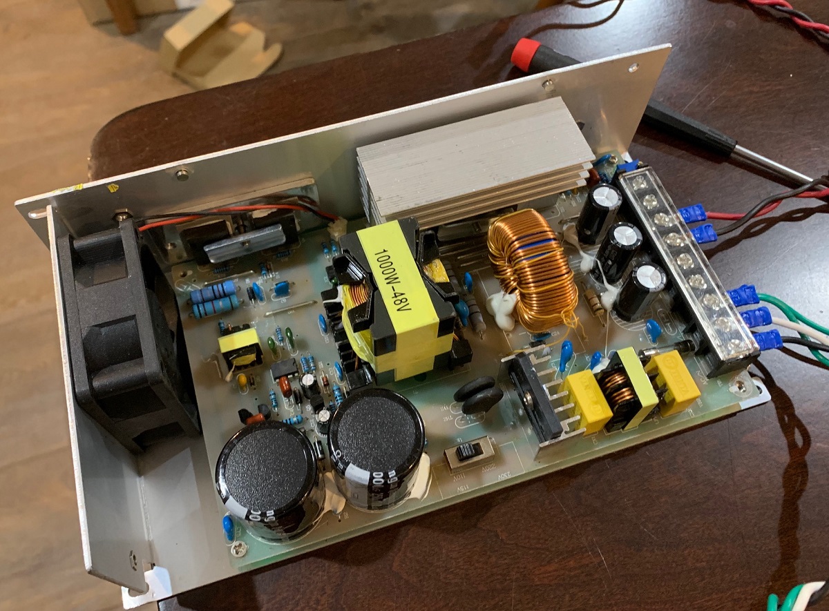
With cover on they look like this:
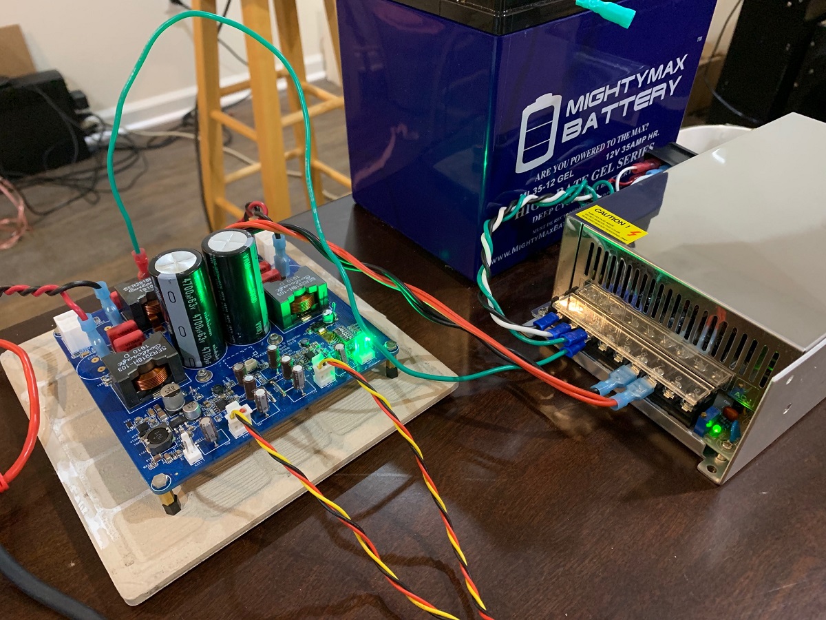
USPick 800w 48v model. KAYPW Switching Power Supply Light Transformer AC 110V 220V To DC 5V 12V 24V 48V Power Supply Source Adapter For Led Strip CCTV|Switching Power Supply| - AliExpress
TPA3255 Reference Design Class D Amp GB
With cover on they look like this:
USPick 800w 48v model. KAYPW Switching Power Supply Light Transformer AC 110V 220V To DC 5V 12V 24V 48V Power Supply Source Adapter For Led Strip CCTV|Switching Power Supply| - AliExpress
Last edited:
This is the output impedance graph for the 3e amp. Is that typical for all TPA3255 amps, or else asked in another way: what is the output impedance of the reference amp across the frequency spectrum?
Sorry, I never measured this - it is a lot of work to do that and I don’t think it will be different. It’s an intrinsic function of The TPA3255 and the output inductor. I use a much lower impedance high current inductor with rectangular copper wire (SER2918-103) which has 2.6mohm DCR. But ultimately, it may be limited by the IC.
The 3e measures 42mohm at bass frequencies, where this matters. That’s quite low. Maybe I can do a measurement at one point, say 100Hz and that will give representative figure.
Last edited:
I found a full suite of measurements of TI's TPA3255 EVM on the QuantAsylum forum including another graph of the output impedance that confirms the 3e-audio graph.
TI TPA3255 EVM
– QuantAsylum
TI TPA3255 EVM
– QuantAsylum
Thanks for the link of Quantasylum products. Their stuff is really well priced and looks like it can automate a lot of testing tedium. The programmable load looks very handy.
Could you please explain me what is the purpose of analog front end NE5532D opamp?
Are they have any effect on gain of the board?
Can we solve low gain issue on PFFB with switch opamps or redesign analog front end?
Are they have any effect on gain of the board?
Can we solve low gain issue on PFFB with switch opamps or redesign analog front end?
The TI reference design uses the NE5532 to perform conversion of SE to balanced drive as unity gain buffer. It can also be configured via jumpers to be a balanced to balanced buffer. I am not sure if you could change the resistors to get gain as the gain of 22dB is intrinsic to the TPA3255 chip. When PFFB is implemented, the feedback is post NE5532 front end. The feedback lowers the gain by 7dB.
It would require a full simulation to see what the effect of adding gain is to the 5532 front end that was specified by TI engineers. Perhaps we could skip it completely if we replaced it with the BTSB using three OPA1656 and two LME49724? We could drive it DC and not have those coupling caps between the front end and the TPA3255 input.
This might improve performance and lower distortion. Although the NE5532 are cap coupled and powered by a single 12v rail so the max swing is +/-6v into the TPA3255 inputs. That may have a safety effect of preventing it from being blown out by over voltage on an input.
That might be so thing to think about for a gen 2 version of this board is to bypass the TI buffer and replace with BTSB with gain.
Last edited:
How will you manage DC-coupling to TPA-inputs - these are self-biasing? And, furthermore, there are no proven benefits doing so in terms of THD and frequency response.
What about this;
TI TPA3255EVM
Ronny bypass the input opamps and get good results. Do you thing is there any bad side effects?
TI TPA3255EVM
Ronny bypass the input opamps and get good results. Do you thing is there any bad side effects?
This is really mean of you bucks bunny. I just can’t read that kind of statement without saying something. Now it’s done and I can keep going on.
By "Reference Design", I was referring to the TI EVM design as the reference design - not that this is a reference design, for which other designs to be compared. The schematic is basically the TI EVM with addition of PFFB and changes to how the connectors and electrical and mechanical interfaces were done.
I quite myself from Post 1:
I quite myself from Post 1:
...develop a new Class D amp based on the TI Reference design...
Last edited:
No offence but i guess bucks bunny and voltwide is the same person 🙂 or could be distant relative.
Nevermind X;
i just checked the official audio front end board from ti they use opa1632 instead of NE5532 couple.
The board is already bypass NE5532 in ti ref board. It has also 12dB gain option to PFFB drop.
Do you think BTSB buffer have an advantage over official one, i guess it neeeds to be test.
Which TI front end board are you taking about and how does it bypass the onboard NE5532? The BTSB is probably better based on what I know about the parts used and the circuit as designed by Jhofland. I’ll be able to test it soon.
- Home
- Group Buys
- TPA3255 Reference Design Class D Amp GB