Maybe you can post a THD VS Freq. sweep graph here? Let`s see how will the distortion go on the higher frequency.
I showed this for one case back on Post 165, distortion is remarkably flat vs higher freuency (higher orders by about 10dB increase from 1khz to 10kHz, but overall THD is about the same):
Last edited:
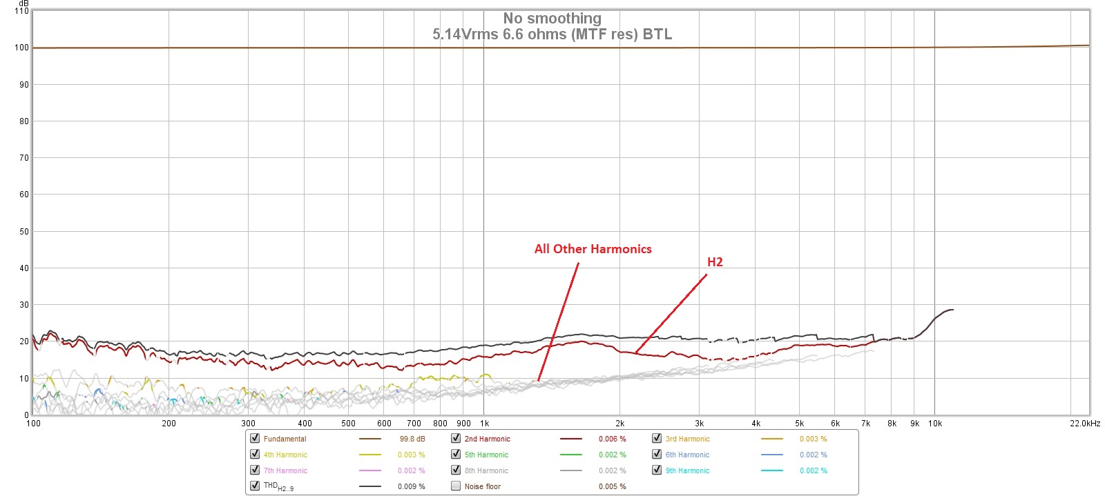
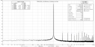
The graph depicts H2=-84dBc and H3=-90dBc @5.14V into 6R6. Not too bad, but not really impressive. The seemingly flat response may be due to the relative high levels even at low frequencies, compared to the TI-EVM. This measured here H2=-92/-100dBc (outAB/CD) - but at 10Vrms into 5 Ohms. My personal mono reference showed H2=-102.7dBc. So there should be room for 10-20dB improvement, specially concerning H2 distortion.
Unless you happen to not mind a bit of H2, so that it sounds more like a SE Class A amp. Do note that this particular implementation is the only one with dominant H2, vs dominant H3 as I have seen on cheap eBay clones, TI EVM, 3E, and Voltwide's amp. It makes this amp uniquely a different sound signature.
I am sorry to say, but this is not the way I would define a "reference" design. "Colored" sound in this context smells more like a weak explanation for design flaws.Unless you happen to not mind a bit of H2, so that it sounds more like a SE Class A amp. Do note that this particular implementation is the only one with dominant H2, vs dominant H3 as I have seen on cheap eBay clones, TI EVM, 3E, and Voltwide's amp. It makes this amp uniquely a different sound signature.
And, btw, I do not expect that this "colored" sound can be distinguished by dbt from a another amp without this color. Moreover I am convinced that besides the measured different numbers there will be absolutely no audible difference.
Just my 2c😉
Voltwide,
Let’s not argue what we as individuals prefer as sonic signatures in our amps. I definitely can hear a difference in a H3 vs a H2 dominant amp - even at same overall THD of 0.004%. There are other aspects such how much contribution from higher odd orders - they add to harshness and listening fatigue.
Reference amp was meant to say it followed TI’s reference design schematic. But if you think 10dB higher distortion of H2 (-80dB THD) is not your cup of tea, everyone is entitled to their preferred amp harmonic distortion signature.
You have give many useful constructive feedback items in the development of this amp, and for that, thank you!
I am still not sure where the extra THD on this amp comes from other than the asymmetric layout of the the inductors. But like I said, I am happy with this level of THD and the profile of its distribution.
Last edited:
Fully assembled TPA3255 Reference Class D amp Interest List
xrk971 24 units USA
Mordikai 2 units USA
Rtep2007 1 unit CZR
Blossom 1 unit NZ
Grahamgraham 1 unit UK
jrosser 1 unit UK
xrk971 24 units USA
Mordikai 2 units USA
Rtep2007 1 unit CZR
Blossom 1 unit NZ
Grahamgraham 1 unit UK
jrosser 1 unit UK
I am thinking of getting the boards built as stereo BTL with balanced line inputs as standard base configuration. It’s more convenient that way as that’s how I will be using these. If you want something else you will need to change the jumpers on the bottom side yourself.
I’m about a week away from placing the fully built GB order - if anyone else wants an amp, please add your name to the list.
I’m about a week away from placing the fully built GB order - if anyone else wants an amp, please add your name to the list.
Hi, I've received the PCB, nice and huuuuge part! It totally scares me about soldering, but you chose the right colour, fits perfectly with my LM1875 compounds for compressions 

Glad that the board got there safely and you like how it looks and feels. It’s a thick heavy board.
I think you (or the shipper) could ad a piece of cardboard but everything is OK with mine. I'll need to work on my skills on others PCB before this one...
I take it this means you are far from having a populated board?
One correction to the schematic and BOM that I caught while building this was the value for R221 which sets the max current before the auto-protect kicks in. 220k is not a valid value. Use 22k for 17A (max value). Unless you want to limit it then use the table in the data sheet to set the appropriate value.
One other thing are the resistors R275/276 for the LED status lights. 1k is way too bright. I would go with maybe 4k7.
Those were the only things I noticed different from the schematic and BOM.
Last edited:
How many bare PCB have you sell ? That kind of recommandation will be lost in the flow of that topic, doing a 2nd one called "building..." ? Or at least in the first page, no time for it now, I think personnaly build that masterpiece next year... 🙂
I can move the above recommendation as an update to post 1 to make sure people see it. Haven’t gotten around to it as no one seems imminent to reflowing solder yet. 🙂
Fully assembled TPA3255 Reference Class D amp Interest List
xrk971 24 units USA
Mordikai 2 units USA
Rtep2007 1 unit CZR
Blossom 1 unit NZ
Grahamgraham 1 unit UK
jrosser 1 unit UK
redjr 1 unit USA
One final test to get high power before I proceed with the production of assembled boards, exposed a few errors on my part. (1) there appeared to be a cold solder joint on one of the legs leading to the bootstrap cap - so I touched and reflowed that with a soldering iron. It may or may not have been a good connection.(2) I saw that my R121 was still at 220k, and so replaced it with a 22k (not sure how that happened because I made a note as if I had changed that). Replacing that fixed the problem and the amp will actually run at higher powers now without hitting the OTW/Error light.
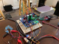
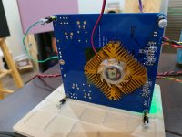
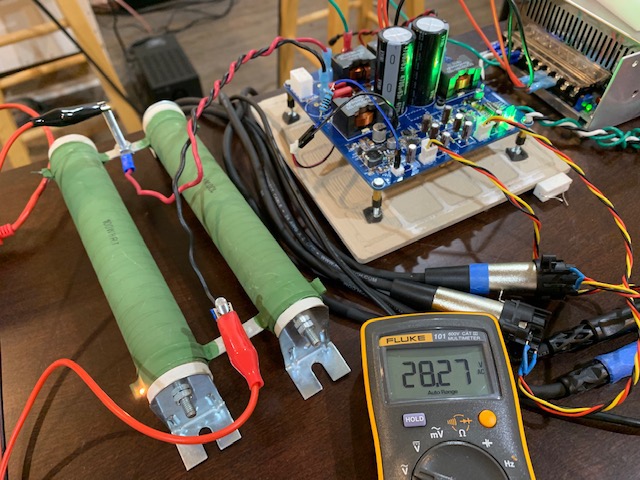
I added a fan cooled CPU to for good measure to run at higher powers. I am able to get 25Wrms into 3.3ohms with the fan off. I used a 100ohm 1W resistor between the fan and the on-board 12vdc supply to quiet the fan down. Connecting the fan with the on-board PSU seems to generate a -100dB ground loop peak at 60Hz for some reason. Very strange as it is only connected to the on board 12v supply and analog ground. Short story is: us a larger passive heatsink or an external PSU for the fan if you must. Or attach it to a metal chassis bottom plate, as designed.


The measurement of the FFT, THD, and SNR at 8.12Vrms into 3.3ohms shows 0.0021% THD and H2 and H3 about the same relative level now. This is down from 0.0026%THD previously measured at the same setting. Slight improvement. SNR is 127dB as measured.
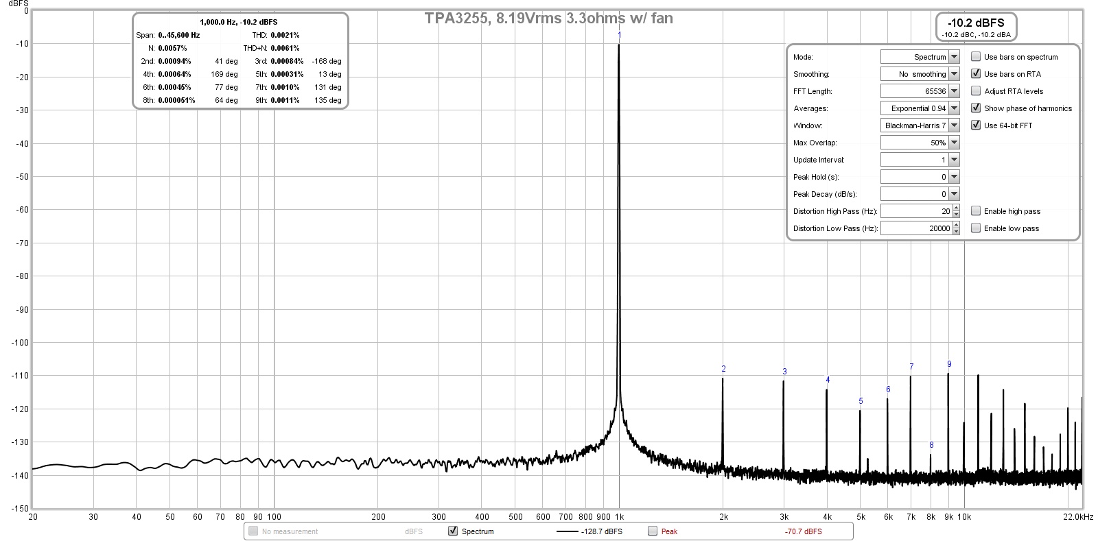
Will have to drag out the big 200w 4ohm resistor to do the big power test.
I added a fan cooled CPU to for good measure to run at higher powers. I am able to get 25Wrms into 3.3ohms with the fan off. I used a 100ohm 1W resistor between the fan and the on-board 12vdc supply to quiet the fan down. Connecting the fan with the on-board PSU seems to generate a -100dB ground loop peak at 60Hz for some reason. Very strange as it is only connected to the on board 12v supply and analog ground. Short story is: us a larger passive heatsink or an external PSU for the fan if you must. Or attach it to a metal chassis bottom plate, as designed.
The measurement of the FFT, THD, and SNR at 8.12Vrms into 3.3ohms shows 0.0021% THD and H2 and H3 about the same relative level now. This is down from 0.0026%THD previously measured at the same setting. Slight improvement. SNR is 127dB as measured.
Will have to drag out the big 200w 4ohm resistor to do the big power test.
Attachments
Final test shows 28.27 vrms into 4ohm load (200Wrms) is easily made without issues using the $44 SMPS.

Amp is now fully tested and verified to go to assembled production as balanced input BTL stereo output amps.
Amp is now fully tested and verified to go to assembled production as balanced input BTL stereo output amps.
X, Do you have a rough estimated cost of the populated board yet. Didn't seem like there was a lot of interest to help bring down the cost.Final test shows 28.27 vrms into 4ohm load (200Wrms) is easily made without issues using the $44 SMPS.
Amp is now fully tested and verified to go to assembled production as balanced input BTL stereo output amps.
Edit - I now see it's in the $200-250 range.
Last edited:
- Home
- Group Buys
- TPA3255 Reference Design Class D Amp GB