
Hi! Please tell me, am I using the resistor value correctly? Or do I need to use 10kO to connect the SE?


What about the TA2024 for 300R headphone amp?You don’t want to use a 150W class D for a headphone amp. There will be some residual Class D switching noise (beat frequency from 400kHz and other sources) you might hear, and in event of a pop from turn on/off or when accidentally hot plugging a jack, it will blow your headphones in an instant.
You want Class A and 1W or so for a headphone amp.
That’s a Tripath Class D. As I said, avoid Class D for headphone amps.
It’s like you have screwdriver but you want to use it as a hammer. Will it hammer a nail? Sort of… but not designed for it, nor the best tool. Use the appropriate tool for the job.
Small push pull Class A is ideal for headphones.
If you want to buy a cheap ready to use headphone amp from Aliexpress, get the TPA6120A2. It’s a fantastic performing class AB amp. Look at the slew rate (1300V/usec), the THD (-94dB for 100mW), and the current capability (750mA).
Datasheet:
https://www.ti.com/lit/ds/symlink/t...776&ref_url=https%3A%2F%2Fwww.google.co.in%2F
For example:
https://a.aliexpress.com/_mt7Oq7i
Or
https://a.aliexpress.com/_mLucw9W
Give it small cheap 10-15VA 12vac to 15vac trafo and you are set.
I have used both of these and they work great. Use a small SE Class A JFET preamp to drive them to get a nice SET like tube sound.
No, TPA6120A2 sounds nothing like a Tripath bridge tied load Class D.
It’s class AB, dual rail, linear amp with crazy high slew rate and low noise and low distortion only capable of driving 750mA and impedances maybe as low as 16ohms.
I don’t know what a DHT is - directly heated triode? So a tube based preamp with nice SET harmonic profile? That’s perfect for driving the TPA6120 as a current buffer.
Hello dear friend, Im plannung multichannel amplifier with TPA3251 and TPA3221.
I found schematic for audio auto on off. I make 2 of them for only power up TPA3251 when stereo music is listeing and one couplet from center channel for secondary power supply.
Are the 230V part for the PSU okay? Does they not make problem with the rest of the PCB? What do you think about the routing?


I found schematic for audio auto on off. I make 2 of them for only power up TPA3251 when stereo music is listeing and one couplet from center channel for secondary power supply.
LOF225-23B36R2 for 1x TPA3251
LOF120-20B27 for 2x TPA3221Are the 230V part for the PSU okay? Does they not make problem with the rest of the PCB? What do you think about the routing?
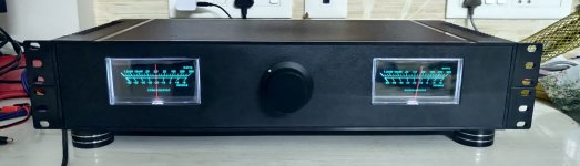
Finally i completed my build and this is how it looks like. The sound is decent. As of now i am running it off my test speakers. The pre-amp is a Nobsound E6. The amplifier makes a pop sound when i power it off. A bit scared due to this to connect them to my main speakers. Any suggestions on how to avoid getting the pop sound ?
Attachments
Last edited:
I’ve bought a smps 48V 8.3A and I have to say I highly prefer it at 48V with enough current compared to lower voltages.Hi all,
what is the best suggested voltage to supply the Aiyima A07?
I think the test that can be found online at 48V vs 32V is highly affected by the low current of the 48V PSU.
Power is endless and detail is very high.
Together with my Klipsch RF82, walls brake earlier than the speakers.
@merlin el mago - I have a EVM board. So i plan to connect your mentioned circuit to ping #6 of the reset switch S1. That should do the trick. Let me know if you think otherwise.
Member
Joined 2018
Additional Note:
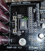
If you feel, too sensitive for supply voltage drop, you can change R2 to 100k ohms.

CyberPit
If you feel, too sensitive for supply voltage drop, you can change R2 to 100k ohms.
CyberPit
Is it applying this feedback?
https://www.ti.com/lit/an/slaa788a/slaa788a.pdf?ts=1702530658470
I think output inductors need to be stiffer to manage the applied feedback.
https://www.ti.com/lit/an/slaa788a/slaa788a.pdf?ts=1702530658470
I think output inductors need to be stiffer to manage the applied feedback.
Hello Everyone.
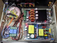
About a month ago, I've bought a chinese TPA3255 board off Aliexpress (Link Here). Powered off a 36V smps PSU (LLC, active PFC). I'm having some issues with one of the channels (mostly the right one) triggering a latched OLP at medium volume. Speakers are 4 ohm, Indiana Line Tesi 261.
The board is mostly default TI's schematic, I've tried replacing a bodge capacitor that got added by the seller on pin 22 and also adding one on pin 1 to ground (gate drive decoupling) with no difference.
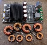
The output filter looks to be decently sized, with 12µH inductors and 1µF capacitors. I've also tried replacing the whole stage with larger inductors (suspecting saturation, as the cores are just 2cm in diameter and wired with 0.7mm enamelled) and better caps (2x0.68uF).
Any idea what could be causing this behavior? The last thing I can try is replacing the PSU with a non-switching one as I've got a suitable 24V 150VA toroidal.
Thanks
Andrea
About a month ago, I've bought a chinese TPA3255 board off Aliexpress (Link Here). Powered off a 36V smps PSU (LLC, active PFC). I'm having some issues with one of the channels (mostly the right one) triggering a latched OLP at medium volume. Speakers are 4 ohm, Indiana Line Tesi 261.
The board is mostly default TI's schematic, I've tried replacing a bodge capacitor that got added by the seller on pin 22 and also adding one on pin 1 to ground (gate drive decoupling) with no difference.
The output filter looks to be decently sized, with 12µH inductors and 1µF capacitors. I've also tried replacing the whole stage with larger inductors (suspecting saturation, as the cores are just 2cm in diameter and wired with 0.7mm enamelled) and better caps (2x0.68uF).
Any idea what could be causing this behavior? The last thing I can try is replacing the PSU with a non-switching one as I've got a suitable 24V 150VA toroidal.
Thanks
Andrea
Attachments
Check the quality of the thermal contact between the chip and the heatsink. Use solvent to clean and remove all the heatsink compound that has touched the pins. The compound has metal powder in it for thermal conductivity. This may be causing some electrical issues. Use a high quality thermal paste sparingly so it doesn’t touch the pins. Make sure heatsink has a mechanical mesa (riser pad) to prevent adjacent parts from touching heatsink.
Also, check that the maximum current setting resistor is the correct value. It looks like it might be correct - it’s the 22k value located near the corner of the front edge.
Also, check that the maximum current setting resistor is the correct value. It looks like it might be correct - it’s the 22k value located near the corner of the front edge.
Forgot to mention that, I had already cleared the heatsink and between pins with isopropyl, gave it a good dry and repasted with some arctic MX5. The heatsink does have a riser pad and doesn't contact any component. The overcurrent resistor is correctly set for 22K.
I've also tried paralleling 100nF caps on every 33nF cap used as bootstrap (marked 333 near the IC), still nothing changed.
I'm at a loss with this board, think I've tried everything possible with it.
I've also tried paralleling 100nF caps on every 33nF cap used as bootstrap (marked 333 near the IC), still nothing changed.
I'm at a loss with this board, think I've tried everything possible with it.
- Home
- Amplifiers
- Class D
- TPA3255 - all about DIY, Discussion, Design etc