@LeRouge I noticed that you routed one of the input wire pairs right next to the AC mains where they come out of the switch/filter unit. That is probably not ideal, even with balanced connections. Maybe this is why you were having some issues previously?
In hindsight, it would have been better to arrange the input/output jacks (left to right) as mains, speaker out #1, speaker out #2, input #1, input #2. This keeps inputs away from current-carrying wires as much as possible. If you had the space (looks like not possible in this chassis) it would be still better to rotate the board 90 degrees clockwise (from the position in the photo) so that the speaker connections are next to the AC mains and the inputs are located all alone in the corner of the chassis, away from other wires and would be shorter inside the chassis itself. They would also not need to be run right above the output inductors, which probably generate some EM field under power.
Finally, you can use shielded microphone cable for balanced inputs and take advantage of some extra shielding on those runs.
Attachments
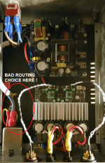
It's the image that gives this feeling of close juxtaposition but in fact it's not a problem, you have to think in 3 dimensions, the connector is placed in height while that of the power supply is 8cm lower and shifted to the left by several cm. And then this type of socket is shielded with a covering connected to the ground and should therefore not be a significant source of emissions. As for the inductors, I have to think about it but I don't think that's problematic either.
In any case, it was a provisional box that served me as a provisional test. I will soon receive 3 new boxes, slightly more spacious (I think they will be almost the same as the Fsatsil one) to make 3 identical amps based on this card for the active amplification of a DIY 3-way speaker. The assembly will be done differently there and indeed the RCA connectors will be placed opposite the power socket.
In any case, it was a provisional box that served me as a provisional test. I will soon receive 3 new boxes, slightly more spacious (I think they will be almost the same as the Fsatsil one) to make 3 identical amps based on this card for the active amplification of a DIY 3-way speaker. The assembly will be done differently there and indeed the RCA connectors will be placed opposite the power socket.

The chassis I used was the Galaxy 2u 230mm x 280mm steel cover from the DiyAudio store and my only regret was not spending the extra $30 or so for the aluminum covers fully ventilated on top.
Hi LeRouge, may I ask which kind of power supply did you use? Thank you!You should also change the interconnect cables.
Like you, I also initially used the cables provided by 3e audio, thinking that they were sufficient, but in the end, when I replaced them, the improvement was immediate. I used AWG 22 i2S cables for this, which I modified by removing the black plastic covering the socket, reducing the socket with pliers so that it fits the pins of the card, covering it with three layers of heat-shrinkable sheath so that once the cables are connected they are perfectly maintained by pressing against each other.
View attachment 1094708
Yes of course ! For this temporary assembly, I used a Connex Electronic SMPS300RS (300W - 36V).Hi LeRouge, may I ask which kind of power supply did you use? Thank you!
But for the final assembly, I'm counting on 48V and I still hesitate to stay on 300W or switch to a 600W power supply.
With 8 ohm speakers I noticed a lack of "energy" and dynamic with the 36V power supply. For speakers of 4 or even 6 ohms, this power supply poses no problem. But it is better that the sensitivity of the speakers is adequate (not too low, >88db) to avoid signal compression, at least that's the feeling I sometimes had. Maybe someone more qualified than me can give the technical reasons (?).
yes, this is the one I also chose. 😉The chassis I used was the Galaxy 2u 230mm x 280mm steel cover from the DiyAudio store and my only regret was not spending the extra $30 or so for the aluminum covers fully ventilated on top.
Same here, running a 2-way active setup with a 3E and a Connex 36V (“overclocked” to 38V) 300W per speaker. Effectively it’s a 600W system. There’s naturally some lack of headroom vs a 48v smps, also visible via the clipping led when trying to drive the 36V system at same SPL. Other than that it sounds great with a ~4 Ohm load.
Finally I chose (3x) SMPS300RS in 48V because on the one hand there will be one amp per ways (active filtering) and, after verification, given the high sensitivity of the woofers (12") as well as the mediums (5") (91db at 1V/1m - 8ohms) and the tweeters (93db at 1v/1m - 6ohms), respecting the max excursions none of them needs more than 110W at 24V to reach almost 112db at one meter per speaker... which is already more than enough... (Which makes 115 dB at 1m by combining the right and left channels without counting the room gain...).
But indeed if my speakers were in passive filtering a single SMPS600RS in 48V would have been more appropriate to deliver the same performance.
The order should arrive at the end of the week with the new boxes and other accessories. I look forward !
But indeed if my speakers were in passive filtering a single SMPS600RS in 48V would have been more appropriate to deliver the same performance.
The order should arrive at the end of the week with the new boxes and other accessories. I look forward !
Last edited:
An amplifier (if I'm not mistaken) is an voltage amplifier, but will still deliver a certain A, so wouldn't the correct way of picking PSU to go by how many W the amplifier is trying to deliver at the voltage you're supplying.
I'm don't know how common it is with home audio, but with car audio it's pretty common that people burn their amplifiers because the cable is too thin.
I'm don't know how common it is with home audio, but with car audio it's pretty common that people burn their amplifiers because the cable is too thin.
I realise that it might have sounded like critique, it was something in between thinking out loud and an open question. I'm sorry if I came across the wrong way. 🙂

Car audio draws power from 12V and boosts it to whatever say +/-50v. Home audio draws from 110/220V which draws less than 10% the car amp current. Boost is less efficient than drop voltage and is more prone to noise. Picking a PSU of course needs to provide generous headroom for amplifier, voltage stability is next- noise and ripple and feedback loop types are the interesting features we typically look for.An amplifier (if I'm not mistaken) is an voltage amplifier, but will still deliver a certain A, so wouldn't the correct way of picking PSU to go by how many W the amplifier is trying to deliver at the voltage you're supplying.
I'm don't know how common it is with home audio, but with car audio it's pretty common that people burn their amplifiers because the cable is too thin.
Speaker cables share similar features
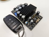
Link please.got the latest variation of tpa3255 from alixpress
https://www.ali express.com/item/1005004804766377.htmlLink please.
https://www.ali express.com/item/1005003202600471.html
https://www.ali express.com/item/1005004777020291.html
these seem to have identical pcb layout
Where is the output filter's capacitor tag? I don't see on the pictures. I'm sorry, if I ask silly question....got the latest variation of tpa3255 from alixpress. mids is wide open and bass is more defined sounds far better than my first generic blue board.
here's the link of the sound test.
I think, I found 😀Where is the output filter's capacitor tag? I don't see on the pictures. I'm sorry, if I ask silly question....
Hi, I have just received my 600 watt Mono 3255 amp & 35 VDC 7amp SMPS from Alli Express. it is intended for my sub system, But correctly I have it ''running in'' in my 2nd system just playing one channel.
https://www.aliexpress.com/item/1005003310223713.html?spm=a2g0o.productlist.main.1.2c773511kyt99v&algo_pvid=2d13aa5c-f3a6-46ef-acc7-2ebbb9029b1d&algo_exp_id=2d13aa5c-f3a6-46ef-acc7-2ebbb9029b1d-0&pdp_ext_f={"sku_id":"12000025138969787"}&pdp_npi=2@dis!NZD!97.07!77.66!!!!!@21021d7b16657795139851696d0736!12000025138969787!sea&curPageLogUid=cMtcCboA5OAL
It sound very good & the bass is definably better defined than my older stereo 3255
Cheers
- Home
- Amplifiers
- Class D
- TPA3255 - all about DIY, Discussion, Design etc