Simply remove those 10uF input caps and use a transformer - that bypasses the whole input section - and it sounds better too - to my ears.
Which transformer, some link please.Simply remove those 10uF input caps and use a transformer - that bypasses the whole input section - and it sounds better too - to my ears.
yes thats the best for about 80 euros....
It only does 150W into 8ohm. What would y'all recommend for 250W/side into 8?
Reduce the distortion of TPA by 15 times .
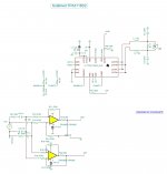
The inputs lead to inverters with 20k ohm , with a gain of 21.5db . If you drive directly the inputs by high impedance 1M current amplifiers , the re injected error gets multiplied by 15 reducing the distortion by the ratio . I tried it on TPA 3116D2 see sublimed TPA3116D2 with great success specially in domain of dynamic . Bellow is the definitive circuit but the power supply need to be elaborated.
The input voltages must be identical 3-3.5v as indicated on datasheet to be 7v max pp .
Attachments
Last edited:
Bellow is the definitive circuit but the power supply need to be elaborated.
What's the function of R15,R20 (39k) please? Just curious.
With TPA3116 running 1.2Mz is flat response if the output LC is adjusted . See Sublimed TPA3116D2 , you can even listen to .nice idea, provided the TPA is unity-gain stable😉
Some call this circuit Holloway others biphase . On this site is the famous My-ref of regretted Mauro Pansea . The 39k is the transconductance resistor transforms the input voltage into output current . It can be reduced to 18k if higher sensitivity is required without any serious drawback.What's the function of R15,R20 (39k) please? Just curious.
The power supply must not be decoupled to get the highest dynamic . I tried the tl423 , excellent at high frequencies but bad at low (bizarre isn't it) . I will try your way , by using AD8008 instead of AD8017 as a pair paralleled can have 0.025 ohm up to 150khz .I also have in mind the power jfet UL1014 as ballast controlled by tl431 only for dc ,leaving the very low impedance of the jfet act as source follower for ac load.
Some call this circuit Holloway others biphase . On this site is the famous My-ref of regretted Mauro Pansea . The 39k is the transconductance resistor transforms the input voltage into output current . It can be reduced to 18k if higher sensitivity is required without any serious drawback.
The power supply must not be decoupled to get the highest dynamic . I tried the tl423 , excellent at high frequencies but bad at low (bizarre isn't it) . I will try your way , by using AD8008 instead of AD8017 as a pair paralleled can have 0.025 ohm up to 150khz .I also have in mind the power jfet UL1014 as ballast controlled by tl431 only for dc ,leaving the very low impedance of the jfet act as source follower for ac load.
Just curious, how did you measure dynamic variation?
It only does 150W into 8ohm. What would y'all recommend for 250W/side into 8?
in post #1142 you get 150W at 8R unclipped. i really think that is enough for home use/home theater....but if that is really to less power...what ever you need😉
more voltage at 8R get more power...therefore look at the IRS2092 boards-->
chris
The only measuring instrument I use ,are my ears .Just curious, how did you measure dynamic variation?
I see😛The only measuring instrument I use ,are my ears .
The only measuring instrument I use ,are my ears .
I think you are in the wrong forum 😉
You do not tune an amplifier by measuring equipment as a "chef" doesn't use chemistry to bring his dish to delicious . If you think as a noob that harmonic distortion numbers bellow 0.3% mean any thing , I advise you to test your ears by TruRTA software (free download) . This generator/analyzer can open as many windows/generators you want . Adjust one generator 1khz to be that harmonic with variable level and another with with 0db with variable 333hz 500hz frequency to be the fundamental. Try to hear bellow 37db about 1.5% the second harmonic and 45db the third about 0.5% . I can not . Now adjust the fundamental 1khz 0db and adjust the second and the third will your scored level . I cannot hear bellow 2% . Many tube amps as 2A3 have sill higher distortions and give far superior sound than many ultra low distorting SS amps . This why if I have to design a better sounding amplifier than my precedent, only my ears can guide me . This is the resulting experience of 50 years of amplifier design , and as ex R&D engineer in servo systems , I fully agree with you I am on wrong forum . As someone said once , you don't cast pearls before pigs .I think you are in the wrong forum 😉
I fully agree with you I am on wrong forum . As someone said once , you don't cast pearls before pigs .
I disagree, I don't believe you're on the wrong forum. One major strength of DIYA (compared to other audio forums) is its tolerance of a wide range of views. If you went to ASR you'd get shouted at so loud you'd want to leave. If you went to Hydrogen Audio you'd get banned pronto.
Certainly you are not alone here with 50yrs of experience - whatever that means. Your argument is pure subjective - that may be fine for you. But be aware that "your ears servicing as measurement equipment" are different from any other ears here. So the result of your experiments cannot be checked or compared and may have little relevance to others. You post your personal opinion, not facts.
This is the advantage of technical measurements: Their results are open to verification by everyone with a standard technical knowledge.
This is the advantage of technical measurements: Their results are open to verification by everyone with a standard technical knowledge.
Here we present ideas and experiences as inspiration and guidance for others. We can pick-up those ideas we find useful and need not give reasons for our choice. Audible impressions count equally as experiences. The problem is they are subjective and more difficult to verify.
I am of the old school and prefer ideas I can follow according to traditional teaching. Other may be ready to go further. A person posting must accept critical comments or even no replies.
I have tried to understand the improvements suggested and I had some difficulties following everything.
I am of the old school and prefer ideas I can follow according to traditional teaching. Other may be ready to go further. A person posting must accept critical comments or even no replies.
I have tried to understand the improvements suggested and I had some difficulties following everything.
Last edited:
Hello, I turn along this idea since some time and would like your advice. I would be happy to test the addition of 2nd Harmonic at the input of a TPA3255 or TPA3251 (or TAS3251). This type of distorsion could ne generated with the Nelson Pass h2 circuit: http://www.firstwatt.com/pdf/art_h2.pdf.
Unfortunatly, this is a single ended type circuit. Can I include such circuit at the input of the TPA, setting the IN-B to the ground and the IN-A to the output of the h2 circuit ?
Or IN-A and IN-B shall evolve symetrically around the 0V ref ?
(using Korg NuTube would be another option).
Thanks for help to see if this maked some sense or not...
Best regards,
JM
- Home
- Amplifiers
- Class D
- TPA3255 - all about DIY, Discussion, Design etc