@KCN
I don't knwo which step-down is used. You can try it.
When step-down input is to low compared to supply voltage you can change it by other.
You should also change input capacitor for 63V rating if its only 50v.
I don't knwo if you can ask the manufacturer.
I will try.
@cacao ambiance
Input switch us replaced by relaiy. When bluetooth is connected the relay will turn input to bluetooth if not the aux is connected to the amps input. Seems to work good 🙂
@KCN
I just go answer about tpa3255 board.
Seller says it works with no problems between 36 and 48v.
AIYIMA TPA3255 Bluetooth 5.0 High Power Digital Audio Amplifier Class D 2.0 Channel 325W*2 AMP DAC PCM5102 Decoding For Phone
I just go answer about tpa3255 board.
Seller says it works with no problems between 36 and 48v.
AIYIMA TPA3255 Bluetooth 5.0 High Power Digital Audio Amplifier Class D 2.0 Channel 325W*2 AMP DAC PCM5102 Decoding For Phone
@hansueli yes, i understand thats how they switch between bt and analogue input. It works fine for personal use. For group use, i am concerned it will be stuck, paired to a friends phone with friend not around to unlock phone and disconnect. That it will be a pain to force it back to analogue input if i want to play something. Unless switching amp off/on resets it? Does it pop during being switched off/on?
@KCN
I just go answer about tpa3255 board.
Seller says it works with no problems between 36 and 48v.
AIYIMA TPA3255 Bluetooth 5.0 High Power Digital Audio Amplifier Class D 2.0 Channel 325W*2 AMP DAC PCM5102 Decoding For Phone
Thankyou. I got the same reply. but the other boards outthere also says 48-50v whereas their regulators are only rated fort 40V. |
so the doubt.
That I will do. 4700uf 63v would be ok??
also the blue 220uf i saw in earlier threads need to be changed. recommended is 1800ufx2. but i think i will replace that also with 4700uf.
Thankyou
I got the e3audio boards cus i thought they best 🙂 but i also wonder what other options there are.... and future options as e3audio dont make amp boards anymore.
Allo has said they are working on a prototype based on tpa3255 so maybe they will release something (or not) and that would probably be more expensive and better than the rest currently available.
Also, the IcePower 100AS uses the TPA3251 but that module is for OEMs only. However, it comes with an onboard SMPS which should be optimized for the chip (one would hope).
@KCN
I just go answer about tpa3255 board.
Seller says it works with no problems between 36 and 48v.
AIYIMA TPA3255 Bluetooth 5.0 High Power Digital Audio Amplifier Class D 2.0 Channel 325W*2 AMP DAC PCM5102 Decoding For Phone
Guys, I mentioned that I did this board working with laptop adapter 19,8V/4A with no problem. Sounding like tpa3116 some about 50W. Btw from laptop adapter heatsink is room temperature and from my Psu it is getting hot even on idle or very low volume. Some magic....
Last edited:
Originally Posted by AnatoliyHill View Post
Wow, Dear Think mentioned original topology contain 2#4700mkF which almost double more I have in my box. Is this a main reason for lack of bass I am having? Furthermore I have only one capacitor enstead of two, think it worth to take of sink enable mates see the topology for further decision.
doc ---> As written already - no.
Chris, it is looks so: one cap blue cap for both rails. Since there is only one cap and two channels one working on two and it is far less than is should be. In overall it is looks very strange this tpa3255 board have limited total caps capacity. Even cheap tpa3116 keep 4000mkF onboard.
hi anatoliy
Doc is principal right about bass and µF on the rails.....but in your second pic(complete board) i try to check the pcb traces ....its not sharp....and it looks like that the blue cap 220µF/50V is connected to PVDD_CD pin 31,30, 29. so its not according to the datahseet!!!
and it slooks like that the trace also go from PVDD_AB pin 38,37,36 ! so its 1 cap for both rails?!!!!
maybe somebody with better eyes can confirm this
...but with your "loudness" or volume concern it has nothing to do
chris
Attachments
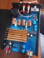
@AnatoliyHill : please ask questions; is does look like there are only 2 shared caps for the power rails: the big one at input and the blue one, close to the chip.
Capacitors are power buffers; enough is enough, there is no influence on output volume. If not enough, bass will distort/sound weak at high volume.
About output volume: TPA3255 has a fixed gain of 21,5dB where tpa3116 has a few options and is often configured at 26dB or higher. So if you use a low voltage signal like a phone output, the 3116 will give more output/ be louder, with the same power supply voltage.
If you use a small mixer or headphone amp (anything with higher output signal voltage) as input, and turn it up, then the 3116 will distort earlier then the 3255 but the 3255 will be about as loud before distorting, if power supply voltage is the same. Once you give 3255 higher power supply voltage and the stronger input signal, it should be louder.
Hi 3eaudio!Sir, Why 1800µ/63V? will single 4700µ/63V do?. I have a few good Elna 4700µ/63V lying around.
Thankyou
I was quite busy recently...
Indeed, it does look like flux. The board sounds great, for the moment I am not changing anything.
Thanks.
Hello, I progress on my TAS3251 design. As it belongs to the same familly as the TAS3255, and this thread is the most active on the topic, I would be happy to post my questions here when possibly applicable to the TPA3255. If you see some inconvenience, please let me know.
I have to finalize the LC output stage: values and parts. I have read the SLAA701A, and played with the TI provided excel sheet for calculations.
Bottom line, my idea is to keep the TAS3251EVM values: 7 mH and 0.68 uF.
SLAA701A states:
For the TPA32xx family of devices, a 7-μH inductor is a better value for performance-oriented applications due to improved linearity and generally improved distortion performance over higher inductances.
The 0.68uF copes with 4R or 6R drivers.
The Woofer of my LX-mini is 8R, but is cut at 700 Hz. At 3kHz, it is -30 dB. So it won't be affected by the bump above 10kHz. A 4R full range ensures the upper part of the spectra. So it should be OK to go to with those values.
Do you believe that this is correct ? Any mistake in my reasoning ?
For the parts, I aim at quality but reasonable choices: not esoteric, but not cutting the corners. Making a custom design is the opportunity to have tweaks normally done on Aliexpress boards afterward included in a clean fashion from the beginning.
As of the parts. From the sale SLAA701A, the best coils qre Wurth 7443630700. They cost about 6€ each. For just lower quality, other candidates are the coilcraft
MA5173-AE of the EVM board. A bit more than 5.80€, so no big price difference.
Alternate candidate with still acceptable quality are the coilcraft UA8013-A, which are coupled coils => 2 coils in the same box. 5€ for the combined coils. Interesting for space and cost perspective.
My intention is to go with Wurth coils, except if someone compared them to coilcraft UA8013-A and did not noticed much difference.
For the Caps, I consider MKP capacitors, as in the EVM. Any better alternative to explore ?
In parallel of those caps, I will have CERM, 1000 pF, 50 V, ±5%, C0G/NP0 (designed in but not installed in the EVM board)
[FONT=Arial, serif][FONT=Arial, serif]
[/FONT][/FONT]Any further advice for the LC ouput section ?
[FONT=Arial, serif]Best regards,[/FONT]
[FONT=Arial, serif]
[/FONT]
[FONT=Arial, serif]JMF[/FONT]
The Woofer of my LX-mini is 8R, but is cut at 700 Hz. At 3kHz, it is -30 dB. So it won't be affected by the bump above 10kHz. A 4R full range ensures the upper part of the spectra. So it should be OK to go to with those values.
Do you believe that this is correct ? Any mistake in my reasoning ?
Although the nominal impedance of the full range driver is 4R, it's approaching 7R at 10kHz. I've always wondered if the LC filter should be based on the nominal impedance or the impedance at frequencies above 10KHz.
Mike
I've always wondered if the LC filter should be based on the nominal impedance or the impedance at frequencies above 10KHz.
Mike
You are not the only one to wonder at this😀
Although the nominal impedance of the full range driver is 4R, it's approaching 7R at 10kHz. I've always wondered if the LC filter should be based on the nominal impedance or the impedance at frequencies above 10KHz.
The important parameter is the resistance (rather than the impedance) as that's what's needed to provide damping. So I'd go for the latter one - the real part of the impedance >10kHz is going to have the most impact on the frequency response of the output filter.
Ok, So I understand that I should consider an higher driver resistance at 10 kHz.
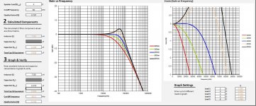
Maybe 7 mH and 0.47uF would do the job. 4R is flat up to 20kHz, 6R is + 0.5 db at 20kHz, and 8R is +07 dB.
Link to the tool: http://www.ti.com/tool/lcfilter-calc-tool
Maybe 7 mH and 0.47uF would do the job. 4R is flat up to 20kHz, 6R is + 0.5 db at 20kHz, and 8R is +07 dB.
Link to the tool: http://www.ti.com/tool/lcfilter-calc-tool
Attachments
Last edited:
It is not the real part of the impedance that increases with frequency but the imaginary part in series with this real, i.e. the inductive component. And this imaginary part disconnects the real part thus preventing damping at high frequnecies.The important parameter is the resistance (rather than the impedance) as that's what's needed to provide damping. So I'd go for the latter one - the real part of the impedance >10kHz is going to have the most impact on the frequency response of the output filter.
As a rule of thumb, with a real speaker you may consider the output LC-filter resonance undamped.
I believe most class d amps have a zobel circuit to flatten out the rising impedance of the speaker/driver, but I don't know how they come up with the component values. Your fr driver has a 3.3 ohm voice coil resistance and .29 mh voice coil inductance. Since you are probably using BTL, would the zobel calculation be based on half these values?
Looking at the different EVM and reference designs (TIDA) using the Akira familly, they all use 10 mH, and either 0.68uF or 1 uF. I believe that it is safe to go to those values, even if it doesn't cope with their technical paper on LC filters.
JMF
JMF
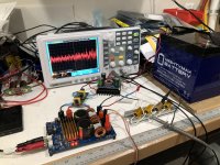
I have a question about the TPA3255’s auto protection and going to fault mode:
I’ve been testing a generic (“Nobsound”) TI reference design of the TPA3255 and noticed that it is very sensitive to input pops and clicks from source material. It will go into fault mode and require power cycle to reset. That’s a problem for me - is it simply the reference design or inherent in the TPA3255 chip itself? I realize it is there to protect speakers - but there has to be a better way to reset (maybe automatically?). The pops were small and came from my DAC switching tracks or changing but rate etc. not ideal but no other amp I have locks me out.
Testing it here with a 12v (13.8v nominal) lead acid gel cell powering a 600w DC-DC step up, followed by a high current CLC with flat wire CoilCraft.
Attachments
- Home
- Amplifiers
- Class D
- TPA3255 - all about DIY, Discussion, Design etc