The light blue trace should only connect + and - of two capacitors to put them in series. Please use a multimeter to measure whether this circuit is connected to +, -, or something else (shouldn't be the case).@Roland968 You also wrote that I can change part of the scheme. when you have the necessary photos, could you guide me on the right path to finalize this board?
Then separate these traces at the red markings.
After soldering in the capacitors, make the yellow connections. Make sure you have good insulation.
But first let's see what's going on with the other two capacitors.
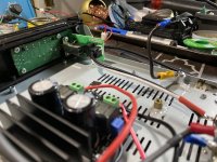
Unfortunately, I didn't take a photo, but I soldered them out and made sure that they - pvdd capacitors connected in parallel. With an operating voltage of 50v 1000ufYes, thanks, but you would also need to remove the two large capacitors between the coils and take a picture of the circuit board underneath. These capacitors are presumably also connected in series.
What is the voltage of these capacitors?
@RuslanK35
If they are already parallel and not in series, everything is ok.
I would recommend for the four capacitors 2200uf with 50 or 63 volts, no bigger, smaller ESR preferred.
Once you've separated the conductors and rewired everything, check everything again for short circuits with a multimeter.
If they are already parallel and not in series, everything is ok.
I would recommend for the four capacitors 2200uf with 50 or 63 volts, no bigger, smaller ESR preferred.
Once you've separated the conductors and rewired everything, check everything again for short circuits with a multimeter.
Indeed so, I did some deep digging in the TPA3251 data sheet (plus measurements) and the 1W figure for losses seems to only reflect the 36V supply.Before uttering wrong conclusions you better study the data sheet.
On top of that there are additional losses for the logic switching supply curcuitry:
GVDD 25mA per full bridge, in stereo 50MA x 12V = 0.6W
VDD 40mA x 12V = 0.5W
In total there is about 0.9W losses on the 36V supply and another 0.9W on the logic side, which is close to the 2W I measured.
A bit high for battery operation, but you can reduce it to 1.25W (for casual listening) with a 12V supply voltage for the whole system.
Last edited:

PVDD power draw is proportional to the souind level.
At lower listening volumes, and especially when idling, the 12V supply losses can be higher than that of PVDD.
For the battery pack in my dual TPA3251 system, I devised a series/parallel switch that makes the pack output either 32 or 16V.
16V mode conserves power quite a bit, idling at 2.5W instead of 4W...
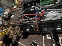
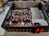
I am utilizing a Teac Chassis I have left over after gutting the machine sometime ago. Its the Teac A H01 Dac Amp unit. I installed a TPA3255 board I have into it and was going to gift it to frined, however I cant get any sound form it at allers some crude pics of the proof of concept build just to test it out while waiting for real speaker binding and Rca's. Ive checked continuity form all point to point of the wiring and its spot on. feeding it with external 48v supply. This bord did work no issues. Its the Shui Yuan TPA3255. What am I over looking? for he signal I have one ground a shared on the makeshift rca terminal Im going fro the center pin of Left and Right to L and right on the 3 pin signal connector, and the ground is one wire also just to center pin of the signal 3 pin connector.
Attachments
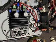

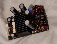
Another TPA3255 mod, replace all the cap with Nichicon HE + little Pana FC (had this cap lying in my desk for long time) , 3 pairs cap near the inductor place in series so i make it simple by removing them and replace with 2x1000uf 50v Nichicon HE, The original inductor so small so i replace them as well with 15A 10uH.
This board is so dirt cheap and can handle 48v, so its very very suitable to handle my Home Theatre Tactile Transducer, just put a Noctua fans above it i think it should be fine.
This board is so dirt cheap and can handle 48v, so its very very suitable to handle my Home Theatre Tactile Transducer, just put a Noctua fans above it i think it should be fine.
Attachments
I get very loud power on pop with my 3e boards. All speaker protection circuits you can buy appear to share GND between L and R speakers, which will not work for this type of amplifiers.
Are there compatible speaker protection circuits?
Alternatively, can mono speaker protection circuits be used in multiples to get around this?
Are there compatible speaker protection circuits?
Alternatively, can mono speaker protection circuits be used in multiples to get around this?
Attachments
I am trouble finding protection boards for class D, any idea where I can look? Thank youYou need to look for speaker protection for Class D amplifiers that interrupt both the + and - line. With classic protections, only + line is interrupted, - line is common, which is generally not allowed for amplifiers in class D.
There's a speaker protector that design for Class D amp, it has 4 switch seperated...I am trouble finding protection boards for class D, any idea where I can look? Thank you
Attachments
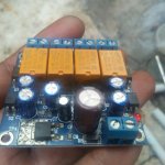
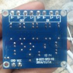
well, im bought it from the local market in Indonesia, but i think those product came from China Mainland...so Ali Express maybe a good start, just find 'Digital Amplifier Speaker Protector' or you can find those by use google image from my photo to find a near market place from your country...Interesting, where can you buy those?
- Home
- Amplifiers
- Class D
- TPA3255 - all about DIY, Discussion, Design etc