https://www.aliexpress.com/item/100...yQpguf662PdigT4LKPbEUsjlvh7GRcdgwaXedruFREeTY
Interesting, new product, good base for modification (can use bigger, good quality inductors, bigger size capacitors, etc.)
Interesting, new product, good base for modification (can use bigger, good quality inductors, bigger size capacitors, etc.)
I would need to use an inductor with the LM5010 circuit that is half the size of the one used in the EVM board. Can I use it without worry? I am making a PCB where I am very limited in size. Thank you for your help.
https://cz.mouser.com/ProductDetail/Bourns/SRR4828A-100M?qs=EU6FO9ffTwdroR6PR%2BIjlQ==
https://cz.mouser.com/ProductDetail/Bourns/SRR4828A-100M?qs=EU6FO9ffTwdroR6PR%2BIjlQ==
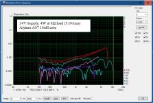
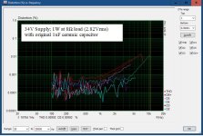
Hi feket663, the inductors are not so bad as it seems. I have this module and tested the cores for a Aiyima A07. Attached the distortion of the Aiyima at 4W with 35V supply and 8.2 Ohm load. The dc resistance of the dual core paralleled to 11uH is only 11 mOhm and they seem to be flat copper wire type.The output filter Approximate match the design. The inductors are 2 x 22 uH, paralelled, = 11 uH as opposed to the original 10 uH recommendation. Unfortunately, better quality, 10 uH Coilcraft or Würth inductor doesn't fit.
If you want to upgrade the sound:
1. put a Wima MKP4 33nF 250V parallel to the 10uF Electrolytic coupling capacitors,
2. exchange the ceramic 1uF (used on this module for the LC filter) to a MKS or better MKP type of film capacitor. See Attachments.
Attachments
Last edited:

Hi,The dc resistance of the dual core paralleled to 11uH is only 11 mOhm and they seem to be flat copper wire type.
If you want to upgrade the sound:
What is the make of the paralleled inductors of 22uH ?
Thanks and regards,
Shadders.
Hi,No idea, there is only the 22uH marking and a date code
Did the inductor come with the board or did you order it from a supplier ?
Thanks and regards,
Shadders.
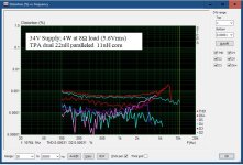
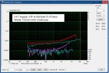
The inductor is the core assembled on the mentioned board on which I reply. Look at the post 4784, this is the board.
Hi,The inductor is the core assembled on the mentioned board on which I reply. Look at the post 4784, this is the board.
Thanks. I checked the Wurth coil referenced in your measurements, and compared to the Coilcraft used by Texas Instrument in their PFFB document. Your measurements show THD much lower for the Wurth output inductor than the TI implementation of the Coilcraft.
After checking Audioscience review the THD is as expected, so perhaps your measurements are showing the THD lower than it should be ?
Regards,
Shadders.
Hi shadders,
I have PFFb implemented. This modification reduce the overall distortion. The output resistance changed from 130mOhm to 25mOhm. This modification gives also more control over the woofer and hence a lot more clarity to the sound.
My PFFb implementation is:
- Input resistor between Opamp and coupling capacitor: 3kOhm
- Feedback only 22kOhm parallel with 100pF (no t-network)
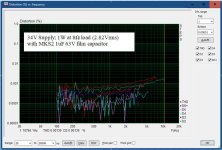
- Output Zobel network with 10 Ohm and 1uF MKS (TI solution: 1 Ohm and 220nF)
I have PFFb implemented. This modification reduce the overall distortion. The output resistance changed from 130mOhm to 25mOhm. This modification gives also more control over the woofer and hence a lot more clarity to the sound.
My PFFb implementation is:
- Input resistor between Opamp and coupling capacitor: 3kOhm
- Feedback only 22kOhm parallel with 100pF (no t-network)
- Output Zobel network with 10 Ohm and 1uF MKS (TI solution: 1 Ohm and 220nF)
Last edited:
Hi shadders,
all the distortion info in the TI documentation is related to the highest supply voltage (51V).
From my measurements Distortion vs. Voltage is best at about 35V.
And the heat dissipation is low at this low voltage, and about 80W vs 8 Ohm is enough output power.
all the distortion info in the TI documentation is related to the highest supply voltage (51V).
From my measurements Distortion vs. Voltage is best at about 35V.
And the heat dissipation is low at this low voltage, and about 80W vs 8 Ohm is enough output power.
Last edited:
but there inductors bulid quality not so goodHi feket663, the inductors are not so bad as it seems. I have this module and tested the cores for a Aiyima A07. Attached the distortion of the Aiyima at 4W with 35V supply and 8.2 Ohm load. The dc resistance of the dual core paralleled to 11uH is only 11 mOhm and they seem to be flat copper wire type.
If you want to upgrade the sound:
1. put a Wima MKP4 33nF 250V parallel to the 10uF Electrolytic coupling capacitors,
2. exchange the ceramic 1uF (used on this module for the LC filter) to a MKS or better MKP type of film capacitor. See Attachments.
Hi trunkdtmc,
I forgot to mention that the inductor saturation current is at about 10A in the 11uH configuration (Würth indictor 22A). This is also fully akzeptable.
My post was addressed to people which have this board and plan to exchange the cores. In my opinion this is not necessary due to the electrical good data and measurements. The sound was improving with these cores in Aiyima A07 and has not notable changed (or further improved) with the Würth cores).
Just ordered this guy from Parts express, New TPA3255 https://www.parts-express.com/Dayto...xlIAL5AIKCMz1LuI_P3tEOw4bDkn7u7LqI9UY=.V6FJTs
anyone try this yet?
anyone try this yet?
yes, i am also using these boards. Overall sound quality is good, except for issues with heatsinks and slightly poor finish. The 12vdc source circuit for the opamp is quite clean, even better than the original a07Hi trunkdtmc,
I forgot to mention that the inductor saturation current is at about 10A in the 11uH configuration (Würth indictor 22A). This is also fully akzeptable.
My post was addressed to people which have this board and plan to exchange the cores. In my opinion this is not necessary due to the electrical good data and measurements. The sound was improving with these cores in Aiyima A07 and has not notable changed (or further improved) with the Würth cores).
Last edited:
53.5 volts for max output. So where to find that outside of bench power? The eval board is quite impressive and cool operating even in PBTL mode against a Klipsch SPL-150 driver. I had the occasion to try it out while waiting for a replacement amp under warranty. First one cooked itself.
I have a TPA3255 amp and am using a 24vdc power supply. I am getting enough volume for my needs. Would there be any gain in using 48vdc?
According to this post, minimum distortion occurs with a supply voltage of 35V (whether this is audible is another matter):
https://www.diyaudio.com/community/...diy-discussion-design-etc.287470/post-6652020
https://www.diyaudio.com/community/...diy-discussion-design-etc.287470/post-6652020
Mr Baldingfast wrote :
According to this post, minimum distortion occurs with a supply voltage of 35V (whether this is audible is another matter):
https://www.diyaudio.com/community/...diy-discussion-design-etc.287470/post-665202
I made up a linear PS today by nicking bits from another dormant amp. The supply gives 42vdc. I have only run it for an hour or so and can't really say if it makes any difference yet. It may be that the presentation is a bit more beefy but the overall presentation which I like is still there. Turning it up is a hoot as there is obviously plenty of power and within sensible limits it all holds together.
Had a long session with 42v and felt that it did not match the SQ of the 24v probably due to the better filtering of the 24v. There was no reduction in volume between the two which surprised me.
At 35V dc supply TPA3251 delivers lower RDson, lower THD and higher efficiency than TPA3255.Voltage is best at about 35V.
- Home
- Amplifiers
- Class D
- TPA3255 - all about DIY, Discussion, Design etc