Have you tried using metal standoffs? My 3e Audio amp had a slight ground hum when I used nylon standoffs so I switched to brass standoffs and the the hum is gone and the amp is dead silent.
I haven't tried metal standoffs, but at one point in my experimentation I explicitly tied the mounting pads to chassis ground with wires. It had no effect upon the hum.Have you tried using metal standoffs?
Given all of the observations, I'm wondering if the problem isn't the fact that both amp modules tie AGND to the same ground internally, combined with the source tying the two signal grounds (RCA cable shields) together itself.
Yes, that's correct practice for many class-D amp boards, and defintely correct for 3e-audio and TI evaluation boards. These boards have audio ground / power ground contacts exposed at their underside mounting points, and these are intended to make electrical contact with the chassis.My 3e Audio amp had a slight ground hum when I used nylon standoffs so I switched to brass standoffs
That doesn't necessarily mean that AGND/power GND is always earthed - the AIYIMA A04/A07 amps, for example, have a metal chassis, but there is no earth connection to this chassis and the DC input is often fed by a SMPS with plastic case - thus they have floating earth.
However I consider it best practice to earth the chassis, thus AGND is earthed at the amplifier.
The only caveat is that for unbalanced connections, you should then check that all other devices in your signal chain have floating earth (or are earthed via a 10k resistor) otherwise you may end up with ground loops.
That seems to be the problem in my case. Unfortunately I cannot control the design of the other devices. So, having tried everything else suggested in this thread (thank you to everybody who contributed!), I have found that the only effective means of eliminating the hum is to transformer-couple the inputs to the 3e boards. I discovered this by trying an old Radio Shack "Ground Loop Isolator", which worked.The only caveat is that for unbalanced connections, you should then check that all other devices in your signal chain have floating earth (or are earthed via a 10k resistor) otherwise you may end up with ground loops.
I have some high-quality line-level isolation transformers on-hand, so I'll use a couple of them to improve upon the Radio Shack solution.
Thanks again to everyone.
Last edited:
What about your RCA-input-connectors ? are they screwed into metal back plate ? if so then you create ground-loops in the chassis with the grounding-point of the capacitors !
Aside from this , you should always use shielded input-cables although the shielding is only connected at one end to avoid said ground-loops unless the two RCA-connectors are isolated from the chassis see further down.
Class-D amps float their outputs at 1/2 of railvoltage so they generate heavy ground-currents from their PCB-ground to chassis ground and this requires taking great care of how you wire them to the PSU/chassis, Two separate wires for ground from each module to Star-ground of chassis can cause havoc this way and the only way to minimise this is to join the grond of the two PCBs with as short and heavy wire as posible then take together to PSU-ground from center of that connection
The same way if two ground-connections go from two modules to input-RCA-connectors and are joined there , or even joined at output of preamp 4 feet away you again create a ground-loop..............one thing you can try is to insert a 10 ohm resistor in each ground-connection of the RCA-input-connectors to greatly weaken or break this ground-loop...........
I had this problem in active speaker-boxes with two modules in each box with three grounds going into the active filter from the amps
Last edited:
Nope. They're electrically insulated from the chassis.What about your RCA-input-connectors ? are they screwed into metal back plate ?
Class AB amps create heavy currents on their positive and negative rails whereas class-D amps do it both on the rail and on the ground from the PSU , unless they are discrete and with positive and negative rails
disconnect both input-headers on the two boards . What happens then ? Power up both modules with disconnected input still humming ?
read this and if necesary look for more info on it : http://www.diyaudioprojects.com/Technical/Grounding-Shielding/
Hum gets worse.disconnect both input-headers on the two boards . What happens then ?
There are only two situations in which the hum disappears: 1) inputs are isolated by line-level transformer, and 2) inputs are shorted.
to Gberchin
I have replayed all the info about your hum . Given that the only way the hum disappears really is with shorted input or ( via transformers ) non-connected input grounds when using two modules it seems clear that you get a modulated ground current in the signal-input-ground and which is modulated by the power-ground of the opposing PCB. This is in accordance with dead silence when only using one board as well . Now if the power-ground of board B modulates the input ground of board A and vice versa then the humming is not our only problem because when high output currents of both boards modulate the signal-grounds of their corresponding opposites that will lead to "cross-board-intermodulation" , which I would not even know how to possibly measure. Could end up being a tweeter-killer no known cause ? ! CHECK WITH SCOPE !
My conclusion is : Find the underlying fault in the grounding instead of simply elimination the hum as this is the only true solution to prevent "out-of-space-effects" and possibly quite nasty future surprises . FOR YOUR SPEAKERS AND EARS SAKE FIND THE CAUSE INSTEAD OF COVERING IT UP
When you are using two boards at the same time you are introducing an error in the grounding of the boards somehow . Probably joining their signal grounds from board A to board B in the right spot eliminates all problems completely . Check layout of boards not alone but together , consider them as one. you might even try to pose the problem to manufacturer of the boards
Last edited:
@MalleMike, thanks for your input. The schematic is there in my initial post for everybody to see. I don't know what is wrong, and none of the suggestions in this thread have solved the problem. I am at a loss how to "[f]ind the underlying fault in the grounding instead of simply elimination the hum", and so is everybody else who has contributed. (Can you understand my frustration?) Unless you can suggest how to "[join] their signal grounds from board A to board B in the right spot", my only remaining option is to create independent power supplies for the two amp modules -- either separate rectifiers and capacitors, or possibly that plus separate power transformers. To me, it's just not worth the effort in a salvaged amp.
Respectfully,
Greg
Respectfully,
Greg
Let us consider that there is no error in how you wire the two boards but an error appears when both are connected at the same time .
NOW : if there is no error in your wiring but appears see above then this error must be built into the boards somehow ( Which is quite possible and another reason it should be found if so)
You have , and you connect , two boards to one PSU which happens in 99% of all amps in this world no problems .
Both boards have a grounding-layout on them which is a small signal ground on the input side and a heavy powerground on the output side which are joined at some point on the board .Your boards are two BTL-tied high power amps which have only one power-rail with the speakers connected beteen two outputs which are both at 1/2 of the rail voltage so you can see the ground as the negtive power-rail which it in fact is.
When driven the two output-stages conduct identical but opposed currents , one from the rail and the other to the ground .
So while you get negative voltage modulation on the rail-system you at the same time get poitive voltage modulation on the ground-system
The amps , although switching at very hidh frequency , modulate the rail with a dropping voltage and the ground with a rising one.
So here is what I think is happening to you : The signal one amp generates on its negative supply ( Which is GROUND ) modulates the input of the amps on the other board which in turn :A) causes the hum when both boards are conected and B) will modulate each other when driven with audo signals.
The transformers at the inputs will eliminate the hum but not the boards modulating each other under load ! If you cannot find the solution in the grounding I would split the PSU , which is not a problem if your transformer has two secondary . BUT SOLVE IT ONE WAY OR THE OTHER

As far as I know, the output ground is not connected to the input ground. I have the documentation around here somewhere; I seem to recall that it warned not to connect the output ground to the input, board, or PS ground.Both boards have a grounding-layout on them which is a small signal ground on the input side and a heavy powerground on the output side which are joined at some point on the board .
Unfortunately only one secondary with center-tap.If you cannot find the solution in the grounding I would split the PSU , which is not a problem if your transformer has two secondary .
Meanwhile, while searching Google for a schematic, I came across this thread. I haven't grokked it, yet, but there may be some worthwhile info there.
Every ampliefier has asmall-signal(input!)ground and a powerground on the printed circuit-board itself and there is some point on the printedcirciut.board where they are connected . have a look here for example:As far as I know, the output ground is not connected to the input ground. I have the documentation around here somewhere; I seem to recall that it warned not to connect the output ground to the input, board, or PS ground.
https://resources.altium.com/p/stay-grounded-digital-analog-and-earth-ground-pcb-layout
Sorry I misunderstood. When you said "output ground" I thought you meant loudspeaker negative terminal.
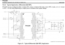
Here is the schematic for mono PBTL mode, from the TI datasheet, for what it's worth.
Here is the schematic for mono PBTL mode, from the TI datasheet, for what it's worth.
Attachments
Last edited:
Unfortunately only one secondary with center-tap
disconnect the two wires at the center tap and you have two separate secondaries
disconnect the two wires at the center tap and you have two separate secondaries
Only one center tap wire.disconnect the two wires at the center tap
- Home
- Amplifiers
- Class D
- TPA3255 - all about DIY, Discussion, Design etc