Not quite sure why you want a switch in between SMPS and the amp. The one before the IEC is enough (unless you’re intending to use one of those low voltage light-up push button switches).
You probably imply it in the diagram but an earth ground to the chassis is advisable.
Just my two cents..
You probably imply it in the diagram but an earth ground to the chassis is advisable.
Just my two cents..
I am planning to build TPA3255 amp with 3e 3255 Stereo board.
Amp board came. other components are on the way.
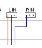
Can please verify the below schematic is correct?
1. Most of the front panel ON/OFF push button used to ON & OFF amp.
2. IEC cable connected with PC Multisocket power strip, AC POWER ON/OFF controlled from there.
3. USB DAC for PC USB & RCA for Mobile, will be used as inputs.
4. using SE inputs only, no Balanced Inputs.
5. Simple Desktop PC amp purpose, as of now
Kindly advise.
Why not connect the GND for the R IN?
Attachments
Thanks a lot for all the inputs and support. please see the answers below.
this is my first DIY assembly in last two decades.
Hi Turion.
1. Yes, same as you mentioned(one of those low voltage light-up push button switches)
2. Grounding is there and I am going to use brass standoffs for PCBs also.
I think the AGND is common, I saw somewhere in this forum or ASR, somebody using same type of connection and it's working in same board. am i right?
BTW connecting that is also possible.
Hope I answered all and them are right.
this is my first DIY assembly in last two decades.
Noted Doc. Thanks, The push button I selected in for Low voltage type, lightup pushbutton - momentary type.Electric arc in DC.
Not quite sure why you want a switch in between SMPS and the amp. The one before the IEC is enough (unless you’re intending to use one of those low voltage light-up push button switches).
You probably imply it in the diagram but an earth ground to the chassis is advisable.
Just my two cents..
Hi Turion.
1. Yes, same as you mentioned(one of those low voltage light-up push button switches)
2. Grounding is there and I am going to use brass standoffs for PCBs also.
Why not connect the GND for the R IN?
I think the AGND is common, I saw somewhere in this forum or ASR, somebody using same type of connection and it's working in same board. am i right?
BTW connecting that is also possible.
Hope I answered all and them are right.
Last edited:
There is reset pin, you could connect push button that use as “Mute” and “Deep Sleep”Doc,
Thanks for the advice.
But IEC socket already has switch and fuse.
Any specific reason, doc?
thanks
Also the fault pin to invert circuit which light up the LED
There is reset pin, you could connect push button that use as “Mute” and “Deep Sleep”
Also the fault pin to invert circuit which light up the LED
thank for the advice bro.
I prefer not play/solder with chip directly.
Though I have some basic electronics knowledge and learning.I am still newbie with soldering iron.
3e has extended those pin to on-board header, you may check that from manual if you don’t have the board on hand
OP By-pass is made. In the mean time by-passed 10uf cap before op.
I want to hear other opinion on sq by who by-pass made too
I got my 3eaudio this morning. Good results with 36V batteries and silver XLR câble but I'm sure it could be way better without OP AMP.
I Would like to try to bypass too. Your bridges can be used without cap modifications ?
Last edited:
D
Deleted member 148505
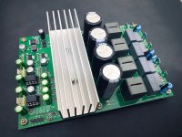
My TPA3255 Stereo BTL Implementation. Transient voltage protection and power on-off pop suppression. ENIG gold immersion PCB surface finish. LM2940 low noise regulator for opamps and nichicon muse input capacitors. Inductors can be changed to 7G23A and heatsink can be changed to ATS-TI1OP-519-C1-R3 (same as EVM)
Will release the PFFB version soon.
Will release the PFFB version soon.
Attachments
After opamp bypass new step is PFFB. Can anyone explain how to mount parts on 3e-audio rev.B version?
Hello guys!
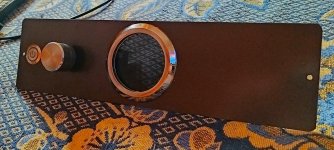
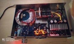
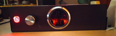
I come to show the conclusion of my vision of a TPA3255 3e Audio.
This is Rev. B from 3e Audio, a Chinese tube preamp, 44VDC linear power supply with 20,000uF.
The amplifier is handling 5ohms speakers with great competence, with very powerful bass without sacrificing the mids and treble.
Despite what is said about this preamp, I was lucky, because my unit has not heard any noise in any volume range, even with the volume at minimum and putting my ears on the tweeters I do not hear any noise.
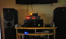
From now on I will do auditions with this setup but right now I can say that I did not hear so much difference for my reference AB Mosfet amplifier, could the tube preamplifier have softened the sound of the TPA3255?
I am enjoying it, I will listen more and come back to give more opinions in a few days.
I come to show the conclusion of my vision of a TPA3255 3e Audio.
This is Rev. B from 3e Audio, a Chinese tube preamp, 44VDC linear power supply with 20,000uF.
The amplifier is handling 5ohms speakers with great competence, with very powerful bass without sacrificing the mids and treble.
Despite what is said about this preamp, I was lucky, because my unit has not heard any noise in any volume range, even with the volume at minimum and putting my ears on the tweeters I do not hear any noise.
From now on I will do auditions with this setup but right now I can say that I did not hear so much difference for my reference AB Mosfet amplifier, could the tube preamplifier have softened the sound of the TPA3255?
I am enjoying it, I will listen more and come back to give more opinions in a few days.
Attachments
I've asked about the Rev. B PFFB modification - no answer yet - and I've posted my best guess before.
"My best guess is this: the 10k resistors, R_op_fb are already there. C_op are probably 22pF on the board and should be 330pF according to the TI PFFB document. I'm not sure that the C_op capacitors really need changing out. The 2x R_in now sit horizontally next to each other at the top of the opamp socket and need to be replaced with 2.7k. The block with the other eight feedback components has only one minor change: one R_fb_gnd now sits horizontally above the two C_fb_out, instead of previously 90 degrees turned. The Zobel on the output is still the exact same."
Nobody responded since I last posted this. I am using the parts names from the 3e audio PFFB document. Confirmations and or corrections greatly appreciated.
My latest 3e audio Rev. B boards also have 680nF C_out capacitors instead of 1uF that the TI PFFB document suggests. I will probably leave those alone.
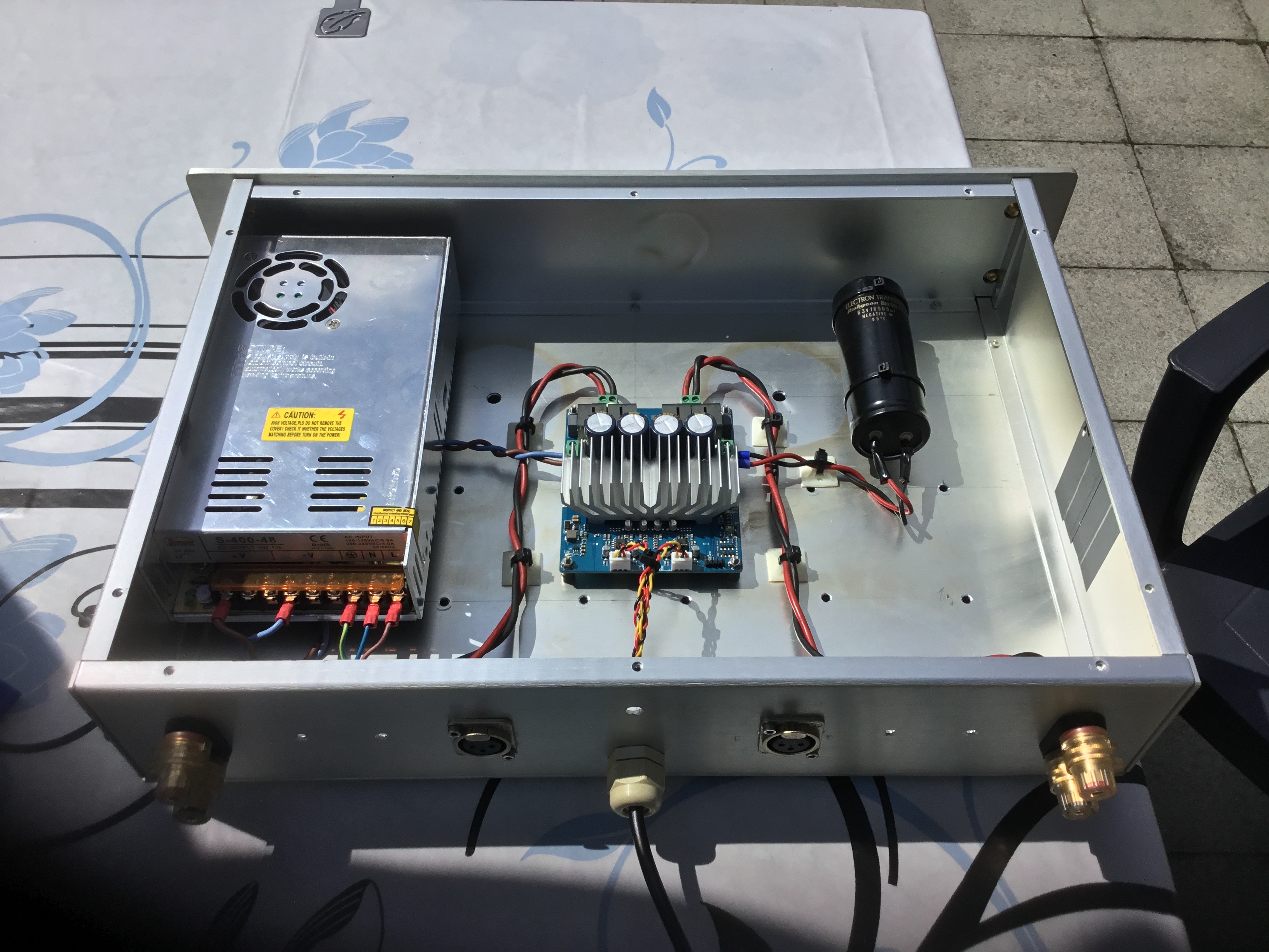
Took the below image from ASR.
What is the purpose of that Big Black Cap there?
Capacitor Bank? with SMPS?
any effect in SQ or performance?
please advice.
Which TPA3255 amp do you recommend? | Page 11 | Audio Science Review (ASR) Forum
What is the purpose of that Big Black Cap there?
Capacitor Bank? with SMPS?
any effect in SQ or performance?
please advice.
Which TPA3255 amp do you recommend? | Page 11 | Audio Science Review (ASR) Forum
The large black block capacitor enhances the power supply at the moment of power supply.
The method of connecting a large-capacity capacitor like this is often used.
The method of connecting a large-capacity capacitor like this is often used.
- Home
- Amplifiers
- Class D
- TPA3255 - all about DIY, Discussion, Design etc