Ti evm has the wrong zobel. They are using 6.6 r load (generic) with inadequate capacitance (ti evm and all copies) increase capacitance (calculate the series capacitance) to around 0.75uf and load resistance to 8r
Do you know how to calculate the zobel for common mode? I know the values I need for the resistor and capacitorin SE mode, do I need to divide or multiple them by two?
Hi Amigo )
This has been reported by Rhing a few weeks ago... take a look at his review on previous pages.
ahh thanks!
Last edited:
Basically Zobel needs to be equal or x 1.25 to the load in common mode. So the R needs to be around 8-10R (for 8R load) and capacitance infinite (but of course we cannot use because of power dissipation )
TI is using Zobel that goes to ground to shunt some hi frequency, but overall it does not matter . I attached an image thats self explanatory
Then look at TI and calculate the C and R in series as if its not going to GND
TI is using Zobel that goes to ground to shunt some hi frequency, but overall it does not matter . I attached an image thats self explanatory
Then look at TI and calculate the C and R in series as if its not going to GND
Attachments
Last edited:
Did you carry out emc measurements in a professional lab with your class-d pcbs? If so I would be very interested in measuring plots. I have been testing electronics in an approved lab over 20yrs and can say that the outcome most of the time differed widely from any of my pre-compliance assumptions and measurements . Deviations increasing directly with frequency...
Your pooring looks quite good indeed - but is no guarantee for blameless emc.
No, I do not have lab measurements for EMI/EMC, and you are absolutely correct... meeting EMI/EMC is always an iterative process that requires measurements, revisions, more measurements and further tweaks. I also spent years of my life sitting in a test lab, and I agree... things are never as simple as you hope when you first set everything up 🙂
Still, there are known and well established techniques and guidelines for at least having a hope of passing (DfX where X=EMI/EMC). I often see little or no effort put into this... plastic enclosures, fly-wired output filters, un-twisted, un-shielded interconnect wires... the list goes on.
Some headache may give the pre-filter outputs close to the TPA-chip routed through single vias. I would doubt the current transport capabilities at that point.
I'm not sure I understand this statement... a single via certainly cannot carry 17A of current, even for a short duration. That would be more than a headache 😱
Very careful attention was paid in this area... VDD pins have 12 vias connecting them back to the power plane, and each pre-filter output has 12 vias connecting it to the output plane which feeds the inductors. There are 5 vias directly adjacent the single-pin output and 7 vias directly adjacent the 2-pin output. Two additional vias feed the bootstrap capacitors from each output. Each via should be able to cope with a continuous 1.5A (these are not filled vias) which means the design will be happy supplying 18A continuous. This aligns with the maximum current the TPA can supply.
And yes, the inductors are the culprit when it comes to extra low THD.
Has anyone specifically characterized exactly what to design for in this area? I know gapped ferrites tend to perform well, and the flat wire types also tend to have an advantage, but those are secondary and tertiary observations. What specifically results in the lowest possible distortion while still maintaining correct filtering of the output? Is the distortion entirely due to non-linearities in the LxI curves of the inductor, or is there something else at play? I would be happy to do some testing in this area, or fabricate some custom inductors if anyone has any ideas.
Regards,
Owen
Hi Owen,
Cool to see your new design!
Have you seen this - This Thing We Have About Hysteresis Distortion - PURIFI
This doesn’t give a clear answer but it’s interesting reading.
Chris
Cool to see your new design!
Have you seen this - This Thing We Have About Hysteresis Distortion - PURIFI
This doesn’t give a clear answer but it’s interesting reading.
Chris
Well, for my knowledge the one and only non-linearity of output inductor is the core. Ultra high linearity of ferrite is not in the focus of the mainstream so you will not find helpful specs. The best bet seem to be gapped ferrite - the more ferrite and more gap, the better. And the more bulky is the coil. It all boils down to minimize magnetic flux excursion at the expense of increased winding turns and copper losses.Has anyone specifically characterized exactly what to design for in this area? I know gapped ferrites tend to perform well, and the flat wire types also tend to have an advantage, but those are secondary and tertiary observations. What specifically results in the lowest possible distortion while still maintaining correct filtering of the output? Is the distortion entirely due to non-linearities in the LxI curves of the inductor, or is there something else at play? I would be happy to do some testing in this area, or fabricate some custom inductors if anyone has any ideas.
Regards,
Owen
It is interesting to see THD significantly increase when replacing the 7uH inductor by its 10uH counterpart. Data sheet shows same DCR of windings in both cases. In other words the exact same winding structure is utilized but core gaps make the difference.
Last edited:
Well, for my knowledge the one and only non-linearity of output inductor is the core.
I bought nanocrystalline cores, I'll try in the next amplifier. Wurth experts say they are better than ferrite
I know nanocrystalline toroids from Vakuumschmelze. With their ultra high permeability these are excellent wideband transformers and common mode chokes. On the other hand the closed magnetic circuit makes them useless for storage chokes, which is our focus here. Or are there gapped nanocrystalline cores available now?
Hello,
i just received my 3Eaudio 3255 amp. My aim is to drive it with my DSC2 DAC with 10K:10K output transformers, but it just not drive 3255. The sound is unrecognizable. While if i connect dac to preamp and preamp to 3255 sounds good. But i want to use 3255 without any preamp. Can anyone help me?
i just received my 3Eaudio 3255 amp. My aim is to drive it with my DSC2 DAC with 10K:10K output transformers, but it just not drive 3255. The sound is unrecognizable. While if i connect dac to preamp and preamp to 3255 sounds good. But i want to use 3255 without any preamp. Can anyone help me?
Thanks,
just solved, changed position of j3 an j4 from SE to DIFF. Now i sounding goog but low gain. I never measured output voltage of balanced output of DAC, but i suppose that due to transformers is not enoght high. Anyway now i can listen without any stuff.
just solved, changed position of j3 an j4 from SE to DIFF. Now i sounding goog but low gain. I never measured output voltage of balanced output of DAC, but i suppose that due to transformers is not enoght high. Anyway now i can listen without any stuff.
Thank you for that link. Gapped nanocrystalline is really new to me and looks quite promising. This may be the superior material actually.😎Black, Al 250
Manufacturer Welcome! | ПАО <<МСТАТОР>>
Sorry for intrusion, i just trying 3EAudio TPA 3255 powered by switching Connex electronics PSU at 30V. Can anyone suggest if it worth power amp by a linear PSU at 48V?
What i can expect as SQ upgrade?
What i can expect as SQ upgrade?
3D Audio ? 3E Audio ? tell us more please )
For your info guys.
TPA32xx All in One Amplifier | 3e Audio
3E Audio has just released their new Finished TPA32XX Amplifier with Sigma DSP
Price is not on site yet... But I spoke with 3E Audio: should be very interesting.(they told me about $99 about 2 months ago)
As per info : For the first batch only they will offer OPA1602
BUT ! still no PFFB.... what a pitty !!!
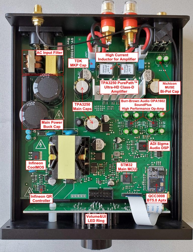
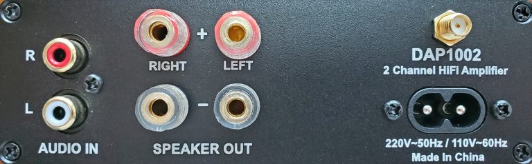
Very Compact size in one Aluminium box
SY-DAP1002-165mm*140mm*50mm – L*W*H
SY-DAP2002 – 193mm*140mm*50mm – L*W*H
SY-DAP1002(TPA3250) – 2channel x 100W(peak)
SY-DAP2002(TPA3255) – 2channel x 200W(peak)
Pop noise free design no matter Power ON/OFF or AC lose
Bluetooth 5.0 with Aptx and BLE support
SigmaDSP(ADAU1701) for audio processing(analog and digital)
LED Ring visual display for user interface (volume,BT,status,etc)
Offortable user EQ tuning directly access into SigmaDSP
TPA3250 TPA3255 Bluetooth 5.0 with DSP Processing Integrated Power Supply All in One HiFi Amplifier| | - AliExpress
Enjoy... 🙂
Sorry for intrusion, i just trying 3EAudio TPA 3255 powered by switching Connex electronics PSU at 30V. Can anyone suggest if it worth power amp by a linear PSU at 48V?
What i can expect as SQ upgrade?
For what it's worth, I see no differences in measurements between my ultra low noise regulated linear 54V supply, a super cheap ($28) 51V LLC from AliExpress, and another super cheap 24V 2.5A wall-wart style supply.
All have the same THD+N, THD, and output noise. My board has very good on-board regulated supplies, so your results may vary with different on-board supplies, but generally speaking the power supply is a lot less critical than it would be with a linear amplifier.
Regards,
Owen
Nice, thanks for sharing. It is now available )
Who is going to order lol 😀
Happy to see some Coilcraft inductors on final version )
Last edited:
$36 shipping to US and expected delivery 5 weeks? seems a bit extreme...
I agree.
let's wait for Amazon to propose it .. who knows? 😕
- Home
- Amplifiers
- Class D
- TPA3255 - all about DIY, Discussion, Design etc