It's not really about small size, although that is a physical side effect...
You're looking for extremely low series inductance (ESL) in this path, and capacitors with long leads, and physically large bodies will have significantly higher series inductance than a small capacitor with very short leads.
Ideally, you want COG/NPO surface mount caps and you want to use planes for the output and ground. This gives the lowest possible series inductance while achieving the desired capacitance.
Any inductance in this path will prevent the filter from working correctly (presents a high impedance to the high frequency switching fundamental and harmonics) and that means those high frequencies make their way onto your speaker wires where they will be radiated out into space instead of being shunted back to the GND plane. This could manifest as increased EMI or possibly even increased noise at the output.
drMordor is absolutely correct though... those are not the correct caps for this application and are causing more harm than good. The correct way to do this can be seen in the attached image.
Yes, you are right, to add to your point the rationale behind using small capacitors is the reduction of the loop area. A large loop area captures stray EMI and induces noise. However, there are opinions that polypropylene caps in the LC filter do make a difference to the sound, and these Vishays are clean and pretty damn good for the price. Of course, NP0 is still the best in terms of least colouring. The Vishays may look big but they are only 30mm across (for reference the TDK are 15mm) as this amp casing is small , I wanted the 26.5mm ones but they are not stocked. I've not tried the TDK, and I will get some and try it as recommended by @drMordor.
I tried my best to minimize the loop area by having the leads straight down and I designed the daughterboard to ensure that most of the current is still being passed in the original board, so there's a large ground plane between these layers. The inductors are also shielded which reduces stray EMI.
Some other people have tried just upgrading the Output Filter with the TI EVM type Inductors (Coilcraft) and just quality Wima Capacitors. I still haven't seen any reports that this resulted in any real benefits over the originally installed Chinese choices.
The Coilcraft inductors have exceptional current inductance stability for the full range of the TPA power but they do not fit into the casing of the AIYIMA. I chose to use the Wurth dual as they are compact, shielded, and pretty stable. Also to note, the LC filter+Zobel is speaker-dependent and the values in the EVM are set for 4ohm speakers.
I think the benefits you are getting over the originals is knowing the inductor tolerance, lower noise as a result of shielding, and the ability to spec the values right.
Here's my subjective opinion, this is done with the OPA1622.
With regards to the sound quality, the sound of the amp drastically improved after swapping the caps at the input stage. It made a HUGE difference. The bass suddenly appeared, the soundstage opened up, the vocals were very clean, it felt like a new amp and I was thoroughly impressed. It fixed everything wrong with the amp. If you had to choose which to upgrade this is the one. And like I said it made me notice other flaws that I haven't notice, for example, the volume imbalance which I wouldn't have picked up with the muddy sound.
I was already satisfied at this point and I could have stopped here but since I already ordered the parts I needed, why not continue. The output stage upgrade was a different game. As you would have expected, it did not yield such a drastic change compared to the former upgrade but instead, it refined the overall sound signature and I think it has to do with the Vishay cap vs whatever it came with. Before the upgrade, the sound was clean but hollow, almost kind of surgical. Now, the sound is warm, full, musical, and I can say that I wouldn't have it any other way.
Last edited:
All in all we can conclude that distortion of TPA325x designs is dominated by the output inductors so it is a good idea to look for the best ones. There exists a TI appnote comparing measured THD of different chokes confirming this.
Did similar measurements with readily wound inductors and ended up with gapped ferrite pot cores like WE744363xxxx
Customs 360 has compared below a few inductors with TPA32XX chip.
As you can see, inductors with "flat wire" perform better.
PS : sorry for my English )
TPA3255 / TPA3251 / TPA3245 universel - un pour tous - #360customs

With regards to the sound quality, the sound of the amp drastically improved after swapping the caps at the input stage. It made a HUGE difference. The bass suddenly appeared, the soundstage opened up, the vocals were very clean, it felt like a new amp and I was thoroughly impressed. It fixed everything wrong with the amp. If you had to choose which to upgrade this is the one. And like I said it made me notice other flaws that I haven't notice, for example, the volume imbalance which I wouldn't have picked up with the muddy sound.
May i ask what capacitors you used for the input feed.
I am planning on replacing mine as well. 🙂
Finally modded the AIYIMA. I wanted everything to fit in the case, that's why I proceeded with this board.
Wruth Inductors
Vishay MKPs
Wima FKPs
Paired a small cap with the power cap
Forgot to ask... seems you have a very special version of the AIYIMA TPA3255... Look at my PCB, it looks very different and makes any mod complicated.

Daniboun I forgot to take a picture before I delivered the amp.. I only have a picture from half way in the mods.. Some of the visible caps mods you see in the picture didnt give any noticable effect unfortunately. But atleast you see the step down board and temperature board for the fan. I also only have my own ears to go by and very little measurement equipment at the moment. An oscilloscope would have been very tracking down the source of the hiss.
Thanks for sharing )
it already gives a nice idea)
Hi Opc
it looks like one of the best tested (and looking ) tpa3255 that I have seen.
You are also correct in using film caps (or cog) in output filter as this is essential to sound quality and measurements . Also using a 4 layer is standard for good class d sound (and measurements , again) . I am pretty sure you used 2oz copper anything else is sub optimal
I am (very slightly ) concerned about H3 while one of the best , its still higher than what I would like. My own testing shows that filter components contribute significantly to H3 along with loop area (and yes dead time)
I think that you can reduce THD further (by around 3 -5 db , read the posts in the last week by buks bunny)
Hey
I asked me what would be better: Metallized Polyester Film Capacitors and PFFB or
Metallized Polypropylene Film Capacitors without PFFB would be better?
I just asked 3e Audio and unfortunately the used caps are not MKP on they new AMP but TDK MKT b32529
I asked me what would be better: Metallized Polyester Film Capacitors and PFFB or
Metallized Polypropylene Film Capacitors without PFFB would be better?
I just asked 3e Audio and unfortunately the used caps are not MKP on they new AMP but TDK MKT b32529
Many thanks Owen.
Some other people have tried just upgrading the Output Filter with the TI EVM type Inductors (Coilcraft) and just quality Wima Capacitors. I still haven't seen any reports that this resulted in any real benefits over the originally installed Chinese choices.
James.
James,
upgrading the output filter is the only mod which will provide measurable improvements. Opamp rolling doesn't.
agreed! Neither does input coupling cap rolling.😉James,
upgrading the output filter is the only mod which will provide measurable improvements. Opamp rolling doesn't.
Please see the two attached plots and let me know which you would prefer for filtering a 450kHz fundamental and its harmonics.
Regards,
Owen
Both do the same impedance wise at desired 450kHz. Ceramics are more prone to produce oscillation/ringing due to their "notch" impedance characteristics and low ESR. Beside that they fail more easy when overloaded by a voltage spice with enough energy (sourced by the inductor). The Q is much higher. Polymers offer some sort of self-healing capabilities.
The thing i wanted to point out is the capacitance variance with supply voltage at ceramics != C0G/NP0.
Having 1uF at 1V and i.e. 500nF a 50V for a 1uF X7R capacitor does something elementary to your LC-Filter. With a 10uH inductor the frequency shifts about 20kHz..
While ceramics (also X7R and similiar) are a super space-sacer, those things should taken into account.
I'd go for stacked internal construction MKP or the smaller MKTs..
I used those for my projects:
B32671P4105K000 TDK Electronics Inc. | Kondensatoren | DigiKey
May i ask what capacitors you used for the input feed.
I am planning on replacing mine as well. 🙂
For the decoupling caps, I went for low ESR ones and those that can handle higher ripple current, you can go for anything similar. The 220 might be slightly overkill.
UPM1J220MED
EEU-FR1E101
EEU-FS1H221L
For the caps surrounding the op amp
I used the Elna Silmic II RFS-35V100ME3#5 which many of the forumers recommend
Forgot to ask... seems you have a very special version of the AIYIMA TPA3255... Look at my PCB, it looks very different and makes any mod complicated.
It is an adapter board I made for the AIYIMA which sits on top of the original.
Both do the same impedance wise at desired 450kHz. Ceramics are more prone to produce oscillation/ringing due to their "notch" impedance characteristics and low ESR. Beside that they fail more easy when overloaded by a voltage spice with enough energy (sourced by the inductor). The Q is much higher. Polymers offer some sort of self-healing capabilities.
The thing i wanted to point out is the capacitance variance with supply voltage at ceramics != C0G/NP0.
Having 1uF at 1V and i.e. 500nF a 50V for a 1uF X7R capacitor does something elementary to your LC-Filter. With a 10uH inductor the frequency shifts about 20kHz..
While ceramics (also X7R and similiar) are a super space-sacer, those things should taken into account.
I'd go for stacked internal construction MKP or the smaller MKTs..
I used those for my projects:
B32671P4105K000 TDK Electronics Inc. | Kondensatoren | DigiKey
Switching frequency is 450 kHz, but noise is not in time domain, it's in frequency domain. As such noise attenuation is better with what ocs is using as caps for lc filter.
Opc, I am looking at your pcb, do you have a full ground plane? Note that you have 4 traces that output high noise and they should be referenced to a plane, preferably right under. Hi frequency noise likes to travel under the trace (lowest impedance) otherwise return path will increase with all associated problems
Ti evm has the wrong zobel. They are using 6.6 r load (generic) with inadequate capacitance (ti evm and all copies) increase capacitance (calculate the series capacitance) to around 0.75uf and load resistance to 8r
All in all we can conclude that distortion of TPA325x designs is dominated by the output inductors so it is a good idea to look for the best ones. There exists a TI appnote comparing measured THD of different chokes confirming this.
Did similar measurements with readily wound inductors and ended up with gapped ferrite pot cores like WE744363xxxx
Yes correct. Logically only one solution. Inductor is the key, we need to custom make instead of waiting for big companies to care about SQ
Sorry for the many posts but one last thing for those that understand and are willing to learn. There is a capacitor that's perfect for reducing EMI and its free, add a layer call it power. This layer is parallel to gnd and as such its a cap in hundreds of pf that's perfect to decouple 20mhz or more noise , that incidentally its where EMI lives. Do not use 2 layers with Tpa3255, 4 is minimum
Opc, I am looking at your pcb, do you have a full ground plane? Note that you have 4 traces that output high noise and they should be referenced to a plane, preferably right under. Hi frequency noise likes to travel under the trace (lowest impedance) otherwise return path will increase with all associated problems
Hi cdsgames,
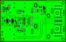
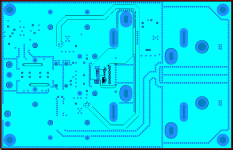
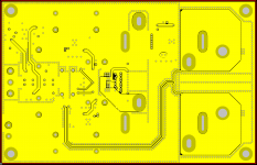
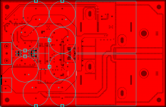
Yes, there is a full GND pour on all 4 layers that covers the entire PCB. These GND planes are via stitched together around the entire perimeter, and there are also local via perimeters around noise-prone nets like the pre-filter amplifier outputs, and the post inductor outputs prior to hitting the final output filter caps.
All of these traces have GND planes both above and below them, and the aforementioned perimeter stitching.
I will attach images of each layer with the GND pours on and hopefully they will make it a little more clear how everything is connected and placed.
Ti evm has the wrong zobel. They are using 6.6 r load (generic) with inadequate capacitance (ti evm and all copies) increase capacitance (calculate the series capacitance) to around 0.75uf and load resistance to 8r
Could you elaborate on this a bit? I'm currently using the Zobel values from the TI PFFB Application Report and they are:
Cz = 220nF
Rz = 1 ohm
Are you saying that you've found a more optimal Zobel filter for use with PFFB? If so I'm all ears! 🙂
Sorry for the many posts but one last thing for those that understand and are willing to learn. There is a capacitor that's perfect for reducing EMI and its free, add a layer call it power. This layer is parallel to gnd and as such its a cap in hundreds of pf that's perfect to decouple 20mhz or more noise , that incidentally its where EMI lives. Do not use 2 layers with Tpa3255, 4 is minimum
Agreed 100%! Inter-plane capacitance can be an effective tool in reducing EMI and improving global capacitance for power nets and anything noisy. Also agreed that trying to lay this thing out correctly on a 2-layer PCB is not a good idea. It can obviously be made to work, but there are a lot of design tradeoffs that need to happen, and EMI/EMC seems to get the short end of the stick.
Hi Opc
it looks like one of the best tested (and looking ) tpa3255 that I have seen.
You are also correct in using film caps (or cog) in output filter as this is essential to sound quality and measurements . Also using a 4 layer is standard for good class d sound (and measurements , again) . I am pretty sure you used 2oz copper anything else is sub optimal
I am (very slightly ) concerned about H3 while one of the best , its still higher than what I would like. My own testing shows that filter components contribute significantly to H3 along with loop area (and yes dead time)
I think that you can reduce THD further (by around 3 -5 db , read the posts in the last week by buks bunny)
Thank you for the kind words! I appreciate you taking a look at the layouts. To answer your questions above:
1. Yes, it is 2 OZ copper. Small cost increase but worth the added current/thermal capacity.
2. I also don't love the overall distortion levels, even though they are lower than anything else I've seen from a TPA3255. I'd be more than happy to look at any specific suggestions you might have to improve here. I still have not tried the Coilcraft variant of the inductors, and that may help somewhat. I also have a variety of other inductors in-house I will try to see if any improvements can be made. Let me know if you have any input here.
Attachments
Hey guys, for those with AIYIMA, can you test the left-right channels.
Seems like it's wrongly labeled? I'm using 3.5mm input, haven't tested the RCA inputs
Seems like it's wrongly labeled? I'm using 3.5mm input, haven't tested the RCA inputs
Hey guys, for those with AIYIMA, can you test the left-right channels.
Seems like it's wrongly labeled? I'm using 3.5mm input, haven't tested the RCA inputs
Hi Amigo )
This has been reported by Rhing a few weeks ago... take a look at his review on previous pages.
Did you carry out emc measurements in a professional lab with your class-d pcbs? If so I would be very interested in measuring plots. I have been testing electronics in an approved lab over 20yrs and can say that the outcome most of the time differed widely from any of my pre-compliance assumptions and measurements . Deviations increasing directly with frequency...Hi cdsgames,
Yes, there is a full GND pour on all 4 layers that covers the entire PCB. These GND planes are via stitched together around the entire perimeter, and there are also local via perimeters around noise-prone nets like the pre-filter amplifier outputs, and the post inductor outputs prior to hitting the final output filter caps.
All of these traces have GND planes both above and below them, and the aforementioned perimeter stitching.
I will attach images of each layer with the GND pours on and hopefully they will make it a little more clear how everything is connected and placed.
Could you elaborate on this a bit? I'm currently using the Zobel values from the TI PFFB Application Report and they are:
Cz = 220nF
Rz = 1 ohm
Are you saying that you've found a more optimal Zobel filter for use with PFFB? If so I'm all ears! 🙂
Agreed 100%! Inter-plane capacitance can be an effective tool in reducing EMI and improving global capacitance for power nets and anything noisy. Also agreed that trying to lay this thing out correctly on a 2-layer PCB is not a good idea. It can obviously be made to work, but there are a lot of design tradeoffs that need to happen, and EMI/EMC seems to get the short end of the stick.
Thank you for the kind words! I appreciate you taking a look at the layouts. To answer your questions above:
1. Yes, it is 2 OZ copper. Small cost increase but worth the added current/thermal capacity.
2. I also don't love the overall distortion levels, even though they are lower than anything else I've seen from a TPA3255. I'd be more than happy to look at any specific suggestions you might have to improve here. I still have not tried the Coilcraft variant of the inductors, and that may help somewhat. I also have a variety of other inductors in-house I will try to see if any improvements can be made. Let me know if you have any input here.
Your pooring looks quite good indeed - but is no guarantee for blameless emc.
Btw I never trusted the boucherots proposed by Ti that much, they are prone to burn with high frequency load applied.And with my special PFFB no boucherots at all are required.
Some headache may give the pre-filter outputs close to the TPA-chip routed through single vias. I would doubt the current transport capabilities at that point.
And yes, the inductors are the culprit when it comes to extra low THD.
Last edited:
- Home
- Amplifiers
- Class D
- TPA3255 - all about DIY, Discussion, Design etc