TPA3255 boxing
@JMF11
Adam Hall 87408V Rack Housing 2HE – Thomann Belgie
I use this top ventilated housing for my TPA3255EVM or 3e audio TPA3255
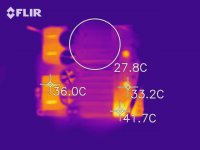
gets hardly warm 24/7
Enjoy...
@JMF11
Adam Hall 87408V Rack Housing 2HE – Thomann Belgie
I use this top ventilated housing for my TPA3255EVM or 3e audio TPA3255
gets hardly warm 24/7
Enjoy...
Attachments
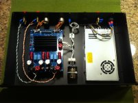
I don’t think the 3eAUDIO TPA3255 needs a fan. I had one in a case with no ventilation and it did not get very hot. I have it in a ventilated case now and it only gets warm.
I’d say it’s important to have an enclosure with ventilation, they are harder to find but worthwhile so your amplifier and power supply don’t overheat.
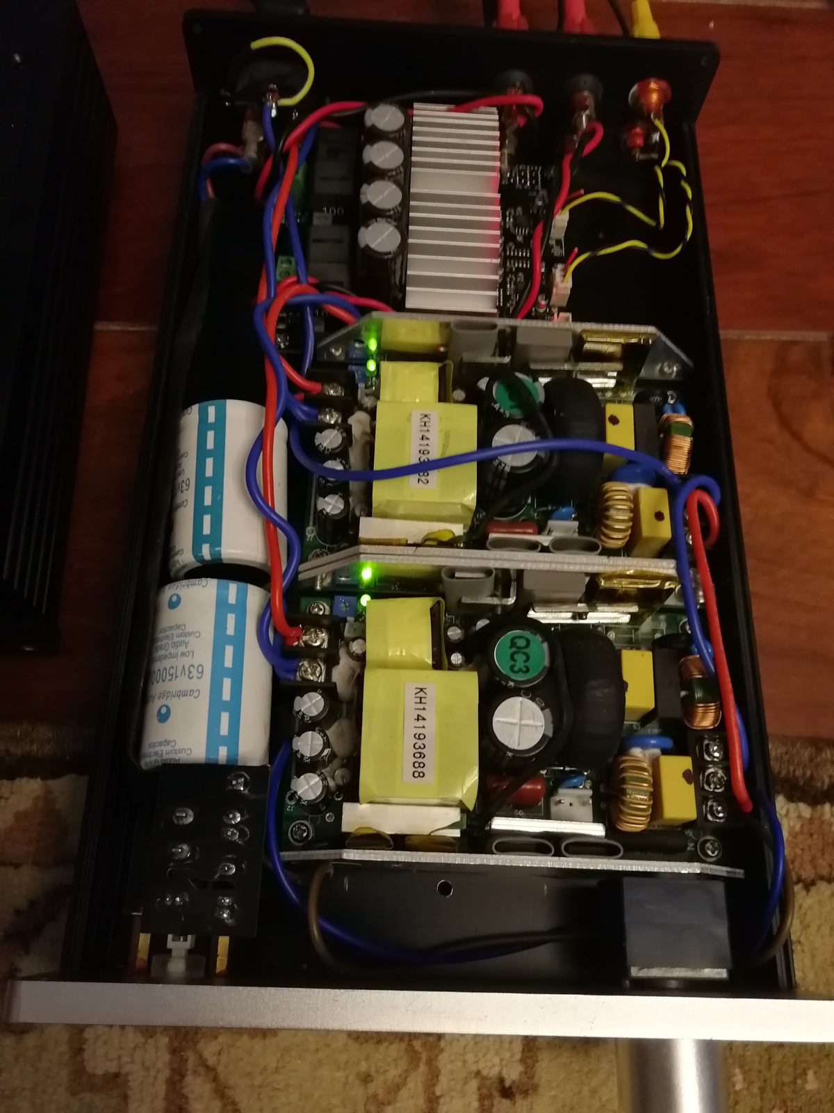
Below is my layout and ventilated enclosure.
BR
Eric
Thanks for the pictures,
Do you have some inflow from the bottom or from the sides ? In my understanding, having holes on the top would not be sufficient.
JMF
Hi
I would say it depends what’s inside the enclosure, for the 3255 it’s not an issue at all.
Plus, finding a nice looking DIY small enclosure w bottom and top ventilation is pretty rare.
BR
Eric
I would say it depends what’s inside the enclosure, for the 3255 it’s not an issue at all.
Plus, finding a nice looking DIY small enclosure w bottom and top ventilation is pretty rare.
BR
Eric
And also what voltage you run on.....have recently upped mine from 40vdc to nearer 50V and it is quite a bit warmer.
@JMF11
Adam Hall 87408V Rack Housing 2HE – Thomann Belgie
I use this top ventilated housing for my TPA3255EVM or 3e audio TPA3255
gets hardly warm 24/7
Enjoy...
Hi Chip
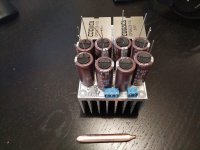
What's that capacitor in the DC line? Values and benefits please
Hi Chip
What's that capacitor in the DC line? Values and benefits please
Yes its a 10000uf with small value good quality Solen bypass cap
To my ears it sounds smoother
Could be placebo 😉
Enjoy...
And also what voltage you run on.....have recently upped mine from 40vdc to nearer 50V and it is quite a bit warmer.
I run mine at 48 volts 🙂
Enjoy...
One thing I am seeing ...all the designs are copying the TI datasheet in regards to input opamps.
A better design is to use dual rails supply removing the GND connection and associated noise.
A better design is to use dual rails supply removing the GND connection and associated noise.
But the advantage of TPA3255 is its single supply.
If dual supply then I will use IRS2092 with IRF6645 or better^^
If dual supply then I will use IRS2092 with IRF6645 or better^^
Its rather easy to use a convertor with dual rails (from single rail) and it has good advantages in regards to noise (GND). In fact , I am using it with dual rail (15V and 50VPvdd) and the 15V rail is changed to dual rail. I am seeing a good decrease of N especially at lower frequency
Yes its a 10000uf with small value good quality Solen bypass cap
To my ears it sounds smoother
Could be placebo 😉
Enjoy...
Thanks for the prompt prompt, can you share a wiring diagram if you have it handy
A better design is to use dual rails supply removing the GND connection and associated noise.
This is not always correct. Unipolar improves PSRR
Thanks for the prompt prompt, can you share a wiring diagram if you have it handy
Positive to + and negative to - for bipolar cap
and one side to + and other to - for nonpolar bypass cap
😉
enjoy...
This is not always correct. Unipolar improves PSRR
Why increase the PSRR ? opamps have rather good PSRR and I use regulators as well (before opamps)
The last few pages of this thread have been a funny summary of my overall feelings with the TPA3255. I've been using a TI EVM for the past 2 years to drive my subs, and have finally grown tired of:
1. Heatsink on the wrong side of the board
2. Heatsink too small for continuous duty
3. No PFFB
4. Poor PBTL implementation
5. Crummy AFE
6. limited inductor choice
7. Zero EMI/EMC considerations
8. Irrational insistence on 2L PCB for an amp that really needs 4L
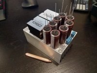
I figured I'd fix the above issues by doing up my own board and going full commit on the PBTL arrangement with proper PFFB and a good AFE. A bottom mount heat pipe implementation for cooling, and provisions for a heatsink large enough for continuous duty at full power output. I'm using the best inductors you can get (Coilcraft AGP4233 / Codaca CPQ4228) and the best caps (parallel NPO SMD). There's room for 8 x 1800uF 80V bypass caps (18mm diameter) with the closest caps sitting only 5.3mm away from the chip pins, and the inductors sitting only 12mm away from the outputs. The latter two items are also courtesy of mounting the TPA IC on the bottom and the caps/inductors on the top instead of trying to make room for a heatsink where you really need the PSU caps and output filter.
It's a 4L PCB so all EMI sensitive traces are buried with proper via shields around the perimeter. The output filter is optimized for low distortion and low EMI. If you mounted on this a heatsink and copper taped the perimeter, you'd pass EMI cert with no enclosure at all.
The AFE uses a pair of OPA1632 op-amps with a complete TI PFFB arrangement. The bi-polar 12V power supplies are generated from a single supply input using Linear Tech's LTC3265 low noise bi-polar supply charge pump. Both the GVDD and VDD supplies for the TPA have dedicated low noise 12V linear regs from a 15V buck supply. You provide between 36-54VDC and the board does the rest.
Attached are some pictures of the preliminary layout and overall arrangement. I will be doing complete measurements on the APx555 and they will be provided here. Thermal measurements will also be provided. PCB's or complete boards will be available in the future once all testing is complete 🙂
Regards,
Owen
1. Heatsink on the wrong side of the board
2. Heatsink too small for continuous duty
3. No PFFB
4. Poor PBTL implementation
5. Crummy AFE
6. limited inductor choice
7. Zero EMI/EMC considerations
8. Irrational insistence on 2L PCB for an amp that really needs 4L
I figured I'd fix the above issues by doing up my own board and going full commit on the PBTL arrangement with proper PFFB and a good AFE. A bottom mount heat pipe implementation for cooling, and provisions for a heatsink large enough for continuous duty at full power output. I'm using the best inductors you can get (Coilcraft AGP4233 / Codaca CPQ4228) and the best caps (parallel NPO SMD). There's room for 8 x 1800uF 80V bypass caps (18mm diameter) with the closest caps sitting only 5.3mm away from the chip pins, and the inductors sitting only 12mm away from the outputs. The latter two items are also courtesy of mounting the TPA IC on the bottom and the caps/inductors on the top instead of trying to make room for a heatsink where you really need the PSU caps and output filter.
It's a 4L PCB so all EMI sensitive traces are buried with proper via shields around the perimeter. The output filter is optimized for low distortion and low EMI. If you mounted on this a heatsink and copper taped the perimeter, you'd pass EMI cert with no enclosure at all.
The AFE uses a pair of OPA1632 op-amps with a complete TI PFFB arrangement. The bi-polar 12V power supplies are generated from a single supply input using Linear Tech's LTC3265 low noise bi-polar supply charge pump. Both the GVDD and VDD supplies for the TPA have dedicated low noise 12V linear regs from a 15V buck supply. You provide between 36-54VDC and the board does the rest.
Attached are some pictures of the preliminary layout and overall arrangement. I will be doing complete measurements on the APx555 and they will be provided here. Thermal measurements will also be provided. PCB's or complete boards will be available in the future once all testing is complete 🙂
Regards,
Owen
Attachments
I figured I'd fix the above issues by doing up my own board and going full commit on the PBTL arrangement with proper PFFB and a good AFE. A bottom mount heat pipe implementation for cooling, and provisions for a heatsink large enough for continuous duty at full power output. I'm using the best inductors you can get (Coilcraft AGP4233 / Codaca CPQ4228) and the best caps (parallel NPO SMD). There's room for 8 x 1800uF 80V bypass caps (18mm diameter) with the closest caps sitting only 5.3mm away from the chip pins, and the inductors sitting only 12mm away from the outputs. The latter two items are also courtesy of mounting the TPA IC on the bottom and the caps/inductors on the top instead of trying to make room for a heatsink where you really need the PSU caps and output filter.
Owen
Seems to be an ambitious project. Looking forward to see the final result )
I imagine you must have been interested in the recommendations and optimizations of similar projects from 360 Customs and XRK Audio?
Hey gents, I'm about to start my first TPA3255 and would love to get some Sound Advice (forgive me).
Going with the 3e-Audio TPA3255. I have one of these suckers laying around collecting dust.
What are your thoughts on sizing and building for future flexibility? I was seriously considering the DAC board from 3e and building it in to the same housing but in reality, the larger housing size to fit all this (the SMPS is pretty big), makes things get expensive.
If you had a $200-250 budget (psu not included), what would you do?
I was thinking of going with this for the volume knob
Any other recommendations? Any preferred enclosure suppliers on AliE? So far, my SMPS and Amp take up about 265 mm x 280 mm x 45 mm.
Thanks!
- Home
- Amplifiers
- Class D
- TPA3255 - all about DIY, Discussion, Design etc