Stereo TPA3116D2 Amplifier With Dual mono Max 2x100W

https://www.pcbway.com/project/shareproject/Stereo_TPA3116D2_Amplifier_26455332.html
https://www.pcbway.com/project/shareproject/Stereo_TPA3116D2_Amplifier_26455332.html

Hi Salva32,Hi @Janux
That red TPA3116 kit looks familiar, similar like XH-M139..
I think couple years ago Mr. @CyberPit shared his detailed experience on that kit.
Please find his post below, there's link to his article :
XH-M139 Issue
This 2.1 amp has (3) flaws:
1 - The leftmost knob is the full range left and right gain. In the middle of the range it has a hiss, but not at the lower or higher end of the range. I keep it pretty high and adjust volume via the laptop and the main volume knob on the right as an acceptable workaround.
2 - When I connect it to power, 90% of the time, the turn on thump is so loud that it goes into protect and does not work. If I disconnect the sub channel, apply power, and then reconnect the sub channel it functions, but I understand there is a mute pin on the...
Hope it helps,
Salwa
thanks for your help.
In the meantime I had already found the blog of the great CyberPit and I implemented some of the modifications he suggested.
Basically I added the auto-mute circuit at power on and off (the version with the mosfet).
I also removed the C40 capacitor (under the heatsink) that caused excessive overheating of the inductors related to the subwoofer and I replaced the 6 inductors with others of 10µH 6.6A purchased on Mouser (542-2000-100-V-RC).
Before I start drawing it... has anyone bothered to make a PCB of the XH-M139 amplifier with all the modifications made by CyberPit? 🤔
Hi @Janux
Glad if you sort it out.
I don't think anyone has ever bothered to redraw / reproduce the "revised" XH-M139.. I saw some layout that took Mr. cyberpit's muting system, but nothing goes as far as that..
Salwa
Glad if you sort it out.
I don't think anyone has ever bothered to redraw / reproduce the "revised" XH-M139.. I saw some layout that took Mr. cyberpit's muting system, but nothing goes as far as that..
Salwa
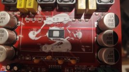
This board is marked XY596

The classic TPA3116D2 circuit uses a 3.3 Ohm resistor in series with a 1nF capacitor for the snubbers.
On this one there are some SMD resistors (I bordered some in green) marked 106 (or 901 reading backwards) is it possible that they put two 10M Ohm resistors (or two 900 Ohm resistors) in series, then in parallel with a 30pF capacitor?

Without removing one from the PCB I can't measure its value correctly. Am I reading the value wrong?
Since this one doesn't have the pop problem at power on/off (or at least not as noticeable as on the XH-M139) and has a much better layout, I ask you.
Does anyone know this board?
Would it be possible with some modifications to improve the bass deficiencies and reduce background noise?
Thanks
The classic TPA3116D2 circuit uses a 3.3 Ohm resistor in series with a 1nF capacitor for the snubbers.
On this one there are some SMD resistors (I bordered some in green) marked 106 (or 901 reading backwards) is it possible that they put two 10M Ohm resistors (or two 900 Ohm resistors) in series, then in parallel with a 30pF capacitor?
Without removing one from the PCB I can't measure its value correctly. Am I reading the value wrong?
Since this one doesn't have the pop problem at power on/off (or at least not as noticeable as on the XH-M139) and has a much better layout, I ask you.
Does anyone know this board?
Would it be possible with some modifications to improve the bass deficiencies and reduce background noise?
Thanks
That is some really odd RC value and arrangement for TPA3116 snubber network.
Have you check what's under the heatsink? Is it really tpa3116?
If it's TPA3116 then maybe you can start with reconstruct the amplifier to TI recommendation and then move your way from there.
For The pop problem I probably will look for what's connected to mute & sdz pin first.
And for tone shaping It will need a tracing on the preamplifier section.
I'm not an expert on PCB design, but IMO this is a neat but a poor layout. The 3 left - 3 right inductor configuration is the first thing that caught my attention.. I saw a hint that the last output from the right chip goes to c24 -> lower inductor -> going back to the top terminal.. it might compromised the signal quality one of the satellite output..
Salwa
Instead this layout is the best in my opinion, the electrolytic decoupling capacitors, even if as usual oversized compared to what is recommended on the datasheet, are much closer to the PVCC pins of the TPA, the fact that the inductors are three per side does not cause any kind of problem. In addition to reviewing the snubbers, the board should be designed to understand where the problem is with the low frequency cutoff.
This time I have a question for the master 🙂
Regarding an old schematic I downloaded from his site for the modifications of the XH-M139.
Dear @CyberPit, shouldn't the capacitors on the outputs that I highlighted in red be connected the other way around?
Also, the labels on the 3 outputs seem to be inconsistent with respect to the LEFT channel, on the right channel and on the sub channel the signal is directed to the N input of the TPA3116.
Is it a typo or am I the one who doesn't understand?
Thanks
Member
Joined 2018
Hi janux-San,
So it will be non-invert totally. According to this, connection to TPA3116 should be the same for all outputs.
CyberPit
You are right, sorry it's my mistake. Just copy from the left...the capacitors on the outputs that I highlighted in red be connected the other way around?
I didn't through at that time deeply. But now I can say, U2B mixer stage inverts the phase and 12dB/oct MFB HPF/LPF's output phase will have a difference of 180 degrees.Also, the labels on the 3 outputs seem to be inconsistent with respect to the LEFT channel, on the right channel and on the sub channel the signal is directed to the N input of the TPA3116.
So it will be non-invert totally. According to this, connection to TPA3116 should be the same for all outputs.
CyberPit
I solved the problem of the polarity of the coupling capacitors automatically by using 2.2µF non-polarized Wima polyester ones as you suggested in the modification to another board.
Thank you very much for the clarifications.
Thank you very much for the clarifications.
Last edited:
Hi
A few weeks ago I received by mistake an XH - M543 board. Ali refunded me and sent me the correct item , so I kept the extra board.
I removed (unglued) the heatshik , under which I found a real (?) - please see the attached picture - TPA3116. I added two screws to the sink and applied thermal paste to the chip.
The sound in my second system is quite good and I'm thinking about "upgrades"...
Change the TL074 (most possibly also a real TI one) to a "better", let say, BB OPA4134 ?
Separate - better PSU for the TL074?
Change the output chokes to 10uH ones, according to the data sheets?
All of the above? Any other ideas?
Thank you in advance
Attachments
- Home
- Amplifiers
- Class D
- TPA3116D2 Amp