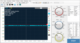
Running a second test for different gain levels, same setup.
As i don't have differential probes, i wont trust the noise levels that much.
Different gain levels does not change the dc-offset.


As i don't have differential probes, i wont trust the noise levels that much.
Different gain levels does not change the dc-offset.
Attachments


Dc offset left is very high compared to any 3116/18 I ever measured dc offset for.
😕😕😕
Outputlevel matters (inputlevel too), at listening levels highest I saw was 708mV DC when at same time board with removed RCsplit reached 36mV.
708mV is way more than 20mV (left channel) and 3mV (right channel).
Datasheet states 1.5-15mV so roughly within the specs, am i not?
Don't know actually why the channels differ "so much", the board is hardly used.
Edit:
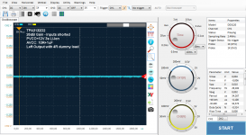
So i connected my dummy load to the outputs (4R 50W), dc-offset drops down to <0.1mV on both channels.
The residual noise if from the scope.`🙂
Is therer anything else that needs to be measured now?
Attachments
Last edited:
Yes, it's a DDS120/BM102:
BM102 BM102 50MHz 2-CH USB-Analog-Oszilloskop - Silber + Grau - Kostenlose Lieferung - DealExtreme
Probes used are TP6100, guess they are the provided ones, just grabbed them from the desk.
I wont call it scope, it's more like an indicator. The provided software is buggy and shows glitches from time to time. The version running here is a "custom build" with some improvements. There's a thread over at eevblog regarding this scope where we "reverse-engineered" looked more deeply into the hardware to get an OS-software up and running.
SainSmart DDS120 & DDS140 USB Oscilloscope - Page 1
It's pretty much an USB streamer (FX2LP) with an ADC attached to it's parallel port with a noisy frontend. You'd better go for an OWON VDS1022(i) if you want an USB scope.
http://www.eevblog.com/forum/testgear/owon-vds1022i-quick-teardown-(versus-the-hantek-6022be)/
I never shared dc offset befor with shorted inputs in posts in this thread. How would input and outputlevel matter with shorted inputs?
Thanks for the info, it looks really slick. It won't be for the really near future though, busy schoolyear but I'm glad there are cheaper options than a standalone oscilloscope.
I never shared dc offset befor with shorted inputs in posts in this thread. How would input and outputlevel matter with shorted inputs?
I searched to whole thread and can't find any dc offset provided by your except
http://www.diyaudio.com/forums/class-d/237086-tpa3116d2-amp-848.html#post4547291
Performance parameters in the datasheet are given for Vin=0V (shorted) and RL=4-8R.
That's what i now verified. If you measured it differently please be so kind to post detailed information of what you measured under which circumstances.

? Please interpret the plot correct. The peaks are the switching representation of a 1kHz sine wave signal. The dc-offset is zero.
Due to the lack of any output/reconstruction filter you won't see the waveform directly.
Due to the lack of any output/reconstruction filter you won't see the waveform directly.
If I interpret what your saying and your tpa chip is equal to 3116/18, then it seems to have a servo in input. Then all DC starts at LC filter here ? When RCsplit gives 0mV DC on your ampboard no matter what level why does it multiply DC levels by 20 with LC filter. I guess you didn't receive Wiener or do I remember incorrectly you were going to receive one?
oh 28W, is that the big eq/servo, bring up temperature to a level nothing creates small differences anymore ?
I don't have a LC-filter at all and this is no Wiener board.
No matter if I use RC-split or not, I doesn't affect the DC-offset at the outputs. With a load connected there's no DC-offset on both channels, running the outputs unloaded isn't defined. The difference between both channels when unloaded (20mV vs 3mv) will most likely come from the IC itself but really isn't an issue. Having more offset with an LC-filter is most likely due to part tolerances of the used inductors/caps.
Those parts are usually in the +-5-10% range, so i.e. only the inductor can differ up to 20% in worst case.
If you have a board handy, you might try by yourself with completely removed output filters.
I don't know if higher temperatures levels out the situation due to thermal noise, but internal FETs Rds_on will rise up a bit.
Last edited:
Question on bootstrap snubber - Blue/Black board
Apologies if the following question stems from my lack of expertise in electronics:
Q: I see on the Wiki page it's recommended to replace the bootstrap capacitors on the Blue/Black board with better ones. OK, fine. That looks simple enough.
But, should the bootstrap snubber mod done by XRK and others also be done? Or, is this an "either/or" situation?
Thanks everyone,
Mark
Effective thermocoupling between inputtransistors could be near perfect when chip is at very high temperaturelevel, gaindifferences between inputtransistors then might not exist and give ~0V dc
Well, it's zero here with input = 0V, so no/minor thermal effects. Would guess, additional offset is introduced by the LC-Filter, but thats something you can easily validate as you have some chinese boards laying around.
Anyway, the question of interest was, will the RC-filter at AVCC will affect DC-offset? Nope, as seen on here. I also can't think of how to get 700mV DC-offset at all?
Anyway, the question of interest was, will the RC-filter at AVCC will affect DC-offset? Nope, as seen on here. I also can't think of how to get 700mV DC-offset at all?
Last edited:
DC offset on the output could be caused by DC offset on the input.
The AC coupling caps on the input normally take care of that, but if you've got a bad cap or flux residue or something else that's pushing DC current into or out of one of the pins, that might do it.
The AC coupling caps on the input normally take care of that, but if you've got a bad cap or flux residue or something else that's pushing DC current into or out of one of the pins, that might do it.
That's the SMAKN board. I bought one from Amazon and it sounds decent. It's got a lot of options for soldering bridge points to change functionality like gain, PBTL, etc It is missing output snubber and of course, bootstrap snubber. Default gain is set high - good for phone source. $13 is Avery fair price.
Thanks for the info. I bench tested it using my phone (which is known for low volume) for a source and it sounded good. Ultimately I will be using it with a Chromecast Audio, not sure about the output level on that. Generally speaking though, is it better to set the gain on the board to 26 and turn the volume up, or leave as it is and simply lower the volume? I'm assuming you would get better AQ w/ lower gain, but I'm a newb 😱 I hope lowering the gain would also lower some of the line noise, since its a little noisy with a silent source.
This little board is amazing though... pushes my large tower speakers just as hard as my humongous HT receiver which doubles as a space heater 🙂
DIY TPA3116 vs ready to use 3116 amps!
Hi!
I`m interested in tiny D-class amp for my Apple pro speakers (bought for macbook and than realized that they need an amp)
Also can be used with JVC UX-7000 speakers as mini hi-fi system, and Usher X-708 (but I think that 708`s are too big for this amp, aren`t its?)
Read about Tripath`s and TDA chips here and at AG forum (not full threads, first and last 20 pages)
Was looking for ReadytoUse amps but read about YJ Blue/Black boards, that are supposed to be much better than SMSL SA-60 for example.
Is there any sense to build amp for my speakers or just use SMSL ?
Take a look at the dual chip version, it's plug 'n play, all you need is a power supply.
http://www.diyaudio.com/forums/class-d/276622-2x100w-tpa3116d2-2-chips-each-pbtl.html
http://www.diyaudio.com/forums/class-d/276622-2x100w-tpa3116d2-2-chips-each-pbtl.html
- Home
- Amplifiers
- Class D
- TPA3116D2 Amp