Well just one electrolytic and decoupling one side of chip seems connected to PSU gnd, nothing else ???
http://i.ebayimg.com/00/s/MTAwMVgxMDAx/z/mcwAAOSwBahVGPjX/$_57.JPG
http://i.ebayimg.com/00/s/MTAwMVgxMDAx/z/mcwAAOSwBahVGPjX/$_57.JPG
BD isn't fully differential, that is reason TI suggests only commonmode filtering, no differential snubber, no differential capacitor. But like the articles linked/copied earlier, also for AD commonmode filters are suggested if interest is lowering distortion instead of lowering cost.
BD isn't fully differential, that is reason TI suggests only commonmode filtering, no differential snubber, no differential capacitor. But like the articles linked/copied earlier, also for AD commonmode filters are suggested if interest is lowering distortion instead of lowering cost.
Ahhh OK. They "suggest". I wondered why this article mentions differential filter use with bd modulation.... Not getting into another debate. Just wanted to have modulation confirmed so I can move forward with output plan.
Analog Devices : Analog Dialogue : Class D
Ahhh OK. They "suggest". I wondered why this article mentions differential filter use with bd modulation.... Not getting into another debate. Just wanted to have modulation confirmed so I can move forward with output plan.
Analog Devices : Analog Dialogue : Class D
Pasted wrong link. Meant this one....
Understanding output filters for Class-D amplifiers | EE Times
Yes read it, both don't specificly go into BD AD differences, but last does mention downsides differential/commonmode
Yes read it, both don't specificly go into BD AD differences, but last does mention downsides differential/commonmode
Aye. The paper. " Intrinsic Distortion of a Fully Differential BD-Modulated Class-D Amplifier with Analog Feedback". Mentions much about the bd modulation and higher harmonics.
Shame it concentrates on just differential version, as xrk measurements showed better harmonics with the differential snubber on 3116 output.
I really need to get the RC for bootstrap mod & replace bootstrap to see if that works for me.
Has anyone tried the hybrid filters? i.e cap parallelled with resistor?
Last edited:
Wouldn't a parallel cap and resistor cause a virtual short through the resistor unless R was very high?
I am not sure that the lower harmonic distortion in my speaker measurement can be conclusively tied to the amp change. It was small. A better was would have been to drive a dummy load and measure voltage across the dummy power resistor. I don't have a sound card that can do that though as my interface is a USB mic and my sound card input is dead.
I am not sure that the lower harmonic distortion in my speaker measurement can be conclusively tied to the amp change. It was small. A better was would have been to drive a dummy load and measure voltage across the dummy power resistor. I don't have a sound card that can do that though as my interface is a USB mic and my sound card input is dead.
xrk graphs hardly showed anything and where no snubber/differential snubber graphs, NOT the adviced commonmode snubber/the not adviced differential snubber.
Hi guys,
Just a quick question; I plan on switching my amp on through a rotary switch and an external relay board that would first put the amp in standby mode (SDZ pin low) and then, at the next click, toggle SDZ high through a relay (planning on lifting the SDZ pin off my YJ blue board and connecting it to the relay).
the question is, would this hamper the amp's overvoltage/overtemp/output DC protection?
Thanks
Wouldn't a parallel cap and resistor cause a virtual short through the resistor unless R was very high?
I am not sure that the lower harmonic distortion in my speaker measurement can be conclusively tied to the amp change. It was small. A better was would have been to drive a dummy load and measure voltage across the dummy power resistor. I don't have a sound card that can do that though as my interface is a USB mic and my sound card input is dead.
I am not sure that the lower harmonic distortion in my speaker measurement can be conclusively tied to the amp change. It was small. A better was would have been to drive a dummy load and measure voltage across the dummy power resistor. I don't have a sound card that can do that though as my interface is a USB mic and my sound card input is dead.
Wouldn't a parallel cap and resistor cause a virtual short through the resistor unless R was very high?
I am not sure that the lower harmonic distortion in my speaker measurement can be conclusively tied to the amp change. It was small. A better was would have been to drive a dummy load and measure voltage across the dummy power resistor. I don't have a sound card that can do that though as my interface is a USB mic and my sound card input is dead.
I know differences were small, and not conclusive proof. I am just saying it was a shame the referenced study only included differential be modulation as the harmonic change seemed to show " a bit " in your graphs.
What the study seemed to highlight was that bd modulation shows increased higher harmonic distortion at lower input signal levels, they eased at higher levels.
higher than AD at low inputlevels, lower than AD at higher inputlevels
don't select too high gain 😀
don't select too high gain 😀
What the study seemed to highlight was that bd modulation shows increased higher harmonic distortion at lower input signal levels, they eased at higher levels.
For any of you guys interested I have a pair of Cinemag CMLl-15/15B
Input transformers to sale. They replace the 4 input capacitors on
These TPA3116 amps and take them to another level wider soundstage
And deeper tighter Bass. Listing on swap meet.
Input transformers to sale. They replace the 4 input capacitors on
These TPA3116 amps and take them to another level wider soundstage
And deeper tighter Bass. Listing on swap meet.
Last edited:
@all,
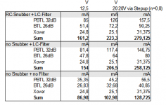
could you boys and girls measure the quiescent current supply voltage of your boards please?
(With note which filter values / components are used)
I just measured my TPA3132D2 boards to calculate the runtime of my boombox at different setups.

As you see, the quiescent current differs alot. I made some further calculation - in conclusion, runtime is 60-100% longer without the filters.
(To be precise 15h vs. 25h averaged with a 9Ah 12V SLA + step-up (n=0.8). At "moderate" levels (85/100dB) runtime is doubled)
RC is 220p+10R (due to small pcb) + LC (Murata 1206 (Z=120R@100Mhz, Rdc = 25mOhm) ferrite + 1nF.
could you boys and girls measure the quiescent current supply voltage of your boards please?
(With note which filter values / components are used)
I just measured my TPA3132D2 boards to calculate the runtime of my boombox at different setups.
As you see, the quiescent current differs alot. I made some further calculation - in conclusion, runtime is 60-100% longer without the filters.
(To be precise 15h vs. 25h averaged with a 9Ah 12V SLA + step-up (n=0.8). At "moderate" levels (85/100dB) runtime is doubled)
RC is 220p+10R (due to small pcb) + LC (Murata 1206 (Z=120R@100Mhz, Rdc = 25mOhm) ferrite + 1nF.
Attachments
Last edited:
For any of you guys interested I have a pair of Cinemag CMLl-15/15B
Input transformers to sale. They replace the 4 input capacitors on
These TPA3116 amps and take them to another level wider soundstage
And deeper tighter Bass. Listing on swap meet.
how should they be connected?
Quick question, think its been answered before but can't find it.
When changing gain resistor values, and can't get values spot on those in data sheets, is it better to use values just above or just below data sheet values?
For example... If I wanted to put in a 20k for 26db gain but can only get 22k or 15k resistors. Which way above or below recommended value is advisable to go with?
Cheers
The nearest, so 22k. (But depends on the rest of the implementation, there is always some margin)
I made myself the calculations for all steps with margins, you have not be exactly at the ds specs.
I made myself the calculations for all steps with margins, you have not be exactly at the ds specs.
- Home
- Amplifiers
- Class D
- TPA3116D2 Amp