Sure, I've removed all of the cheap pots that come with these boards.
Can you just remove the pot as use a pre-amp.
More to the point: does the pot have to be replaced with jumpers or a resistor of some sort?
Can you just remove the pot as use a pre-amp.
More to the point: does the pot have to be replaced with jumpers or a resistor of some sort?
It depends on the circuit and where you bring the signal into the circuit. I typically find the point in the signal path that is most direct (or sometimes more convenient) so I don't need to put any jumpers between the ins and outs of where the pot once was.
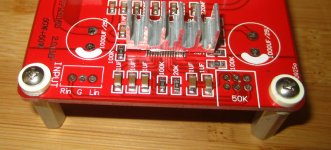
On this board I could bring the signal into the amp at the yellow points if I wanted to use the surface mount caps provided, but I use the blue points and use a better film cap of my own. Hope this helps.
.
Attachments

Thank you, that makes sense.
no problem.... and here's a pic of the board with some parts removed.
Attachments
I have wondered about whether or not poly film caps on the input really sound better than the ceramic ones. What property of the caps make them sound better? I know it's a can of debatable worms but I can't seem to find any quantitative measurements that show that a $5 poly or $200 paper and oil cap gives better signal response than $0.20 ceramic SMD 1uF cap.
I have wondered about whether or not poly film caps on the input really sound better than the ceramic ones. What property of the caps make them sound better? I know it's a can of debatable worms but I can't seem to find any quantitative measurements that show that a $5 poly or $200 paper and oil cap gives better signal response than $0.20 ceramic SMD 1uF cap.
You're right it's a can of worms and there are SO many threads on this elsewhere over the years that there is no point in getting into it here, it will only derail the thread; the only way you can know for sure is to try for yourself
and given how cheap in general 1uf caps are exotic or not, it should be easy enough to determine for yourself.
Please let's not get into caps and measurements and differences blah blah blah. It is SO boring and there is nothing that can be said that hasn't already been said on this and every other audio forum.
Yes, Try some different caps and see if it makes a difference for you.... I've used no fewer than a dozen different pairs of caps with this little guy from dirt cheap to over the top expensive and it was great fun listening to the differences... I enjoy that part of it.
Yes, Try some different caps and see if it makes a difference for you.... I've used no fewer than a dozen different pairs of caps with this little guy from dirt cheap to over the top expensive and it was great fun listening to the differences... I enjoy that part of it.
So you do hear a difference? What was then your preferred cap to use on this amp? Maybe I can solder some wire lead sockets that lets me slip in different caps to test? Getting back in there to remove two perfectly soldered 0805 SMD caps is the only thing holding me back. I don't want to derail the thread or open a can of worms - just would like to know what I should try to get the most bang - given that this amp cost me less than $20 to make.
It depends on the circuit and where you bring the signal into the circuit. I typically find the point in the signal path that is most direct (or sometimes more convenient) so I don't need to put any jumpers between the ins and outs of where the pot once was.
On this board I could bring the signal into the amp at the yellow points if I wanted to use the surface mount caps provided, but I use the blue points and use a better film cap of my own. Hope this helps.
.
I am guessing (could not see the details of the PCB), those two 1 uf caps are the DC blocking caps at the inputs?
If they are, then bringing signals at the blue points would bypass the blocking caps (there are people that do not like using DC blocking caps at the inputs)? Or did I read the PCB trace wrong?
Regards,
No, the idea here is to use better caps and being the signal through the input cap in at the blue dot.
I just tried out the metalized poly film caps by putting an easy to remove jumper across the existing SMD ceramic cap, then soldering the new cap between the RCA jack and the RG174 coax that connects the RCA input to the PCB input. It is a 1uF 63v plastic cased radial lead unit. Not as nice as a 250 volt rated unit. Anyhow, I listened to my test tracks before switching and listened to them after and...
I can't tell the difference. 🙂
I was reading the spec sheet from TI and it seems to indicate using a 2uF may give better bass extension depending on your input impedance. Might be worth it to double up to get 2 uF. But I was hoping to hear more sparkle or micro details but could not honestly say I heard a difference. But now that it is wired this way I can try different caps all I want.
Why would you think 250V rated caps would be better? For film caps bigger voltage means more surface area to pick up that RF noise generated by the output filter. Ideally you should get caps as small (physically) as possible so the ceramic ones that was already in the amp was probably better suited, even if they might have been lower quality. Just get some high quality SMD ceramic caps.
Someone told me to try a 250 v poly film cap because they thought it sounded good. My question of why a physically larger cap would sound better at least seems to have reason to not sound better accessing to your assertion that it is a larger antenna for stray RF from the output stage makes sense. Recall in my earlier post that I did not want to open a can of worms and people said you just have to try for yourself and hear if it makes a difference. Well so far no difference and it would seem like going with as small a cap as possible would make sense. I have even smaller caps than the 0805 size but probably doesn't matter at that size. These are actually xr7 rated at 16 volts made by TDK and they cost $0.80 ea.
You can also try some of the micro electrolytic caps from panasonic or nichicon especially if you want a little higher value. Although they might be too big to fit directly on the board.
seems like it's going on sale today:
Assembled Stereo audio power amplifier TPA3116 2.1CHANNEL CLASS D-in Amplifier from Consumer Electronics on Aliexpress.com
any takers?
what power supply have you guys been using?
Assembled Stereo audio power amplifier TPA3116 2.1CHANNEL CLASS D-in Amplifier from Consumer Electronics on Aliexpress.com
any takers?
what power supply have you guys been using?
I have been using a 24v 6.25A SMPS for the 2.0 and after reading the PS enquiry, changed to a 14V 4A SMPS and there was no loss of volume or sound degradation.A 19 volt 4.65 amp laptop SMPS brick works well for 2.0. You might use two bricks for the 2.1?
seems like it's going on sale today:
Assembled Stereo audio power amplifier TPA3116 2.1CHANNEL CLASS D-in Amplifier from Consumer Electronics on Aliexpress.com
any takers?
what power supply have you guys been using?
Hey,
I just ordered the 2.1 on sale at Ali. Too good to pass up. Hopefully they ship fast!
Kyle
Thank you guys.
How does it compare to lm3886? Anyone?
In an previous meet of the Toronto DIY group, I have the opportunity of hearing both a chip amp (LM3886) and an amp based on TPD3116d2 (based on the reference design I think) for brief moments. To me, the TPA3116d2 was more extended at the high and low frquency end. The LM3886 chip was more "balance". Both sounded fine but a little different. I can live happily with either amp.
However, the cost difference between the two amps is quite large. LM3886 amps require a decent power supply and heat sink. The TPA3116d2 amp is cheap and all one needs is a laptop brick to run it. The performance to price ration is huge!!
My 2 cents.
Regards,
- Home
- Amplifiers
- Class D
- TPA3116D2 Amp