TI answered gmarsh and the stamp-amp mini tpa3132 english guy (I think) tried with 12V avcc I believe and found horrible performance, you were participating in that thread too, I don't recall name really, reminded me of Apple iOs is all I recall, many moons ago 🙂
The horrible cracking disappeared when avcc-pvcc voltage got closer together.
The horrible cracking disappeared when avcc-pvcc voltage got closer together.
The Peerless SLS 830667 driver used in those subs is 8-ohm. The most power you will be able push with a 3116D2 amp is about 30W for that impedance. Even if you get a 4-ohm driver, the max power is about 50W. If you really want to drive 100W out of 3116D2 amp in PBTL mode, you need a 2-ohm subwoofer speaker.
If you want to use the 8-ohm Peerless SLS 830667 driver, you may want to consider a TDA7498 based amplifier board instead. And if you want to use a 4-ohm driver, a TDA7498E based board may be better. In either case, you would need a 36V power supply.
Thanks Ravels - I think I need to do a bit more homework before deciding on a bass solution. My understanding is that this amplifier in 2.1 configuration will deliver about 70 watts into a 4 ohm load, before going into unacceptable levels of distortion. My plan was to source an 8" driver of suitable handling capacity ie 80-100 watts RMS, but whether that will generate suitable bass response in a bucket sub is what I'm trying to establish.
To approach it from the other angle - what would the best bass solution be for this specific amp? Or is it the case that there is no really good solution and the 2.1 configuration is impractical?
I think finding an amplifier to fit a subwoofer speaker solution may be easier (and cheaper) than finding a subwoofer solution to fit a specific amplifier configuration.
With a TPA3116 based 2.1 solution, you can drive 50W into a 4-ohm subwoofer as higher distortion may be acceptable for most people for lower frequencies. The amp should be able to drive 4/6/8 ohm speakers for the other two channels at reasonable volumes for listening to music at home without any problems, especially if the built in crossover in the amp is designed correctly and the low frequencies do not make it to those two channels.
I use a different TPA3116 2.1 amp in my den with an old 10" passive Yamaha Subwoofer (which is rated 6-ohms, 40W nominal, 130W max) and it works quite well. You are not going to get ground shaking bass with this kind of setup, but for listening to music, it can be quite nice.
You may need a better power supply with a 2.1 setup. I found a used 24V 6A AC adapter (which can actually deliver 6A for long periods of time without dropping the voltage or getting hot) and it works quite well with this setup.
Also note that bucket subwoofer implementations deliberately used a driver that was not necessarily a subwoofer driver. I don't know the theory behind this, but something to consider.
The Peerless SLS 830667 driver used in those subs is 8-ohm. The most power you will be able push with a 3116D2 amp is about 30W for that impedance. Even if you get a 4-ohm driver, the max power is about 50W. If you really want to drive 100W out of 3116D2 amp in PBTL mode, you need a 2-ohm subwoofer speaker.
If you want to use the 8-ohm Peerless SLS 830667 driver, you may want to consider a TDA7498 based amplifier board instead. And if you want to use a 4-ohm driver, a TDA7498E based board may be better. In either case, you would need a 36V power supply.
Most folks build a pair so you get 4 ohms connected in parallel.
I can't find this statement in the datasheet compared to the TPA3118. Can you point me in the right direction? Are you refering to "9.1 Power Supply Mode"? This is also valid for the 3118, as the internal LDO structure isn't changed.
If its also valid for the 3118 why isn't it explicitly stated? When I introduced my AVCC RC decoupling mod the pushback (including I think from TI themselves) was that AVCC and PVCC could not be substantially different voltages. But now for the first time we have it in writing that they can be hugely different.
Attachments
What's the difference between the tpa3116 and the 3116D2?
What's the most common circuit board that people use for these mods? Looking to get started modding these and I just need a pure power amp without volume control or anything
What's the most common circuit board that people use for these mods? Looking to get started modding these and I just need a pure power amp without volume control or anything
If its also valid for the 3118 why isn't it explicitly stated? When I introduced my AVCC RC decoupling mod the pushback (including I think from TI themselves) was that AVCC and PVCC could not be substantially different voltages. But now for the first time we have it in writing that they can be hugely different.
Because the 3118 datasheet is older and no one likes to write/correct datasheets? 🙂
So what electronics should go into an amplifier according to you?
I don't see why gain control is a must, tons of people here work with TPA3116 boards without gain control.
Also input cap mods are being done here all the time, I don't see what makes this board special in that respect.
What is your personal experience with TPA3116 / TPA3118 boards?
Ignore my post, sorry. I was being a bit of a bitch. Mom had me annoyed. 😛
Audio tested:
TI answered gmarsh avcc should be at same voltagelevel pvcc for 3118, unlike for example 3110's family. The minute voltagedivider RC put on pvcc for avcc by it self might not create much of a voltage difference, different ground could add to that difference once large high frequency currents go through groundplane, just like 3251 differential inputstage channel inequality caused by that, just like Hypex telling switching ampboards can't have connectors at both ends of pcb, perhaps just like mono configured Wiener processor switching off playing louder with 1-2 ohm speaker, when at that outputlevel and even twice that outputlevel Sanwu3118 doesn't switch off.
....
I then decided to further the concept by supplying AVCC from a 5V LDO. This meant the analogue would have a nice clean supply. Upon building it and testing, I found that it only caused extreme noise on the output, which makes sense for obvious reasons. I then supplied AVCC from a separate PSU and I found that AVCC needs to be within about 500mV of PVCC for it to work correctly.
TI answered gmarsh avcc should be at same voltagelevel pvcc for 3118, unlike for example 3110's family. The minute voltagedivider RC put on pvcc for avcc by it self might not create much of a voltage difference, different ground could add to that difference once large high frequency currents go through groundplane, just like 3251 differential inputstage channel inequality caused by that, just like Hypex telling switching ampboards can't have connectors at both ends of pcb, perhaps just like mono configured Wiener processor switching off playing louder with 1-2 ohm speaker, when at that outputlevel and even twice that outputlevel Sanwu3118 doesn't switch off.
The noise reported for that ampboard isn't likely to be caused by the filmcapacitors on input, nor any other component, although removing the heatsink might affect audible noiseIgnore my post, sorry. I was being a bit of a bitch. Mom had me annoyed. 😛
The noise reported for that ampboard isn't likely to be caused by the filmcapacitors on input, nor any other component, although removing the heatsink might affect audible noise
I think you quoted the wrong person 😛
All one sees is two filmcapacitors for inputsignal coupling, normally these perform better than chinese ceramic class 2 capacitors. The noise some report isn't likely caused by the filmcapacitors...
There's only a meh-quality input cap, too.
Audio tested:
TI answered gmarsh avcc should be at same voltagelevel pvcc for 3118, unlike for example 3110's family. The minute voltagedivider RC put on pvcc for avcc by it self might not create much of a voltage difference, different ground could add to that difference once large high frequency currents go through groundplane, just like 3251 differential inputstage channel inequality caused by that, just like Hypex telling switching ampboards can't have connectors at both ends of pcb, perhaps just like mono configured Wiener processor switching off playing louder with 1-2 ohm speaker, when at that outputlevel and even twice that outputlevel Sanwu3118 doesn't switch off.
Thanks for the the input. What about this "just like 3251 differential inputstage channel inequality", did i missed something? It isn't ground referenced.
I meant the opampsplitters for differential signal as in a 3251 app note:
http://www.ti.com/lit/an/slaa719/slaa719.pdf
http://www.ti.com/lit/an/slaa719/slaa719.pdf
Ah, but this isn't directly related to the LDO problem. 🙂
I'll have a look into this with a 3118 board.
I'll have a look into this with a 3118 board.
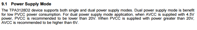
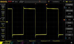
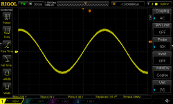
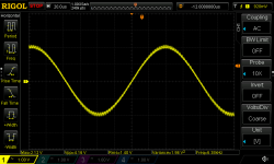
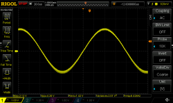
I tooked one of these Sanwu TPA3118 PBTL boards to test. (Thanks to irribeo)
PVCC: 11.7V from 3s Li-Ion
AVCC: Linear power supply Korad KA3050D (locally decoupled with 100n X7R at the AVCC pin)
Output power: 0.5W into 4R (1.41Vrms)
Unmodified PVCC+AVCC locally tied together:

Modified as noted:
AVCC 11.7V:

AVCC 10.0V:

AVCC 7.3V:

AVCC 6.0V:

AVCC: 4.3V:

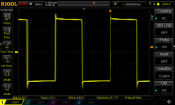
Below 7.3V the gain starts to rise so does the output amplitude. From ~5.5V and below the IC sometimes needs some time to "resyncronise" the switching. Once stable, it runs stable. Below 4.3V the 3118 stops switching.
The midrail supply voltage (audio input) varies with AVCC voltage:
11.7V -> 3.1V
7.3V -> 4.6V
4.3V -> 3.0V
Below 7.3V the static noise increases, so does the gain. I would say, this is directly related to each other.
One thing i find strange is, the voltage at pin GVDD doesn't change over the full range of AVCC variation. Between 11.7V - 4.3V AVCC voltage, GVDD stays at 7.14V.
Beside the increase of idle-noise (static) due to gain variation i can't see nor hear a problem with excessive noise or distortion. So to me, 3118 and 3128 are acting the same at this.
PVCC: 11.7V from 3s Li-Ion
AVCC: Linear power supply Korad KA3050D (locally decoupled with 100n X7R at the AVCC pin)
Output power: 0.5W into 4R (1.41Vrms)
Unmodified PVCC+AVCC locally tied together:
Modified as noted:
AVCC 11.7V:
AVCC 10.0V:
AVCC 7.3V:
AVCC 6.0V:
AVCC: 4.3V:
Below 7.3V the gain starts to rise so does the output amplitude. From ~5.5V and below the IC sometimes needs some time to "resyncronise" the switching. Once stable, it runs stable. Below 4.3V the 3118 stops switching.
The midrail supply voltage (audio input) varies with AVCC voltage:
11.7V -> 3.1V
7.3V -> 4.6V
4.3V -> 3.0V
Below 7.3V the static noise increases, so does the gain. I would say, this is directly related to each other.
One thing i find strange is, the voltage at pin GVDD doesn't change over the full range of AVCC variation. Between 11.7V - 4.3V AVCC voltage, GVDD stays at 7.14V.
Beside the increase of idle-noise (static) due to gain variation i can't see nor hear a problem with excessive noise or distortion. So to me, 3118 and 3128 are acting the same at this.
Attachments
-
 extavcc_7V3_switching.png32.7 KB · Views: 108
 -
 extavcc_4V3.png35 KB · Views: 672
 -
 extavcc_6V0.png32.2 KB · Views: 675
 -
 extavcc_7V3.png32.4 KB · Views: 671
 -
 extavcc_8V0.png32.2 KB · Views: 93
 -
 extavcc_10V0.png32.2 KB · Views: 674
 -
 extavcc_11V7.png32.3 KB · Views: 672
 -
 stock_pvccavcc.png32.3 KB · Views: 668
 -
 extavcc_4V3_switching.png35.3 KB · Views: 103
I meant the opampsplitters for differential signal as in a 3251 app note:
http://www.ti.com/lit/an/slaa719/slaa719.pdf
Don't you need an inductor between G1 and the ground plane for the recommended configuration in the TI app note?
Analog ground is removed from groundplane I think, adding inductor to groundplane would increase voltage difference I would think, because it is created by inductance groundplane, at high frequencies/high currents.
No static is an improvement, no midpoint or DC shift when voltagedifference grows caused by current seems good enough improvement. But maybe when groundpoints AVCC/PVCC would have been close enough together on groupbuy boards no problems would have appeared with DC on output. Easy fix, remove the RC split entirely, maybe better fix, bring groundpoints together if possible.
The 3118 lookalike ampboard does distort a lot, but can't compare to standard Sanwu, Sanwu with different inductors I did compare, that one listens a lot easier 🙂 Again, high current listening situation.
The 3118 lookalike ampboard does distort a lot, but can't compare to standard Sanwu, Sanwu with different inductors I did compare, that one listens a lot easier 🙂 Again, high current listening situation.
- Home
- Amplifiers
- Class D
- TPA3116D2 Amp